Continue to Site

Eng-Tips is the largest engineering community on the Internet

Intelligent Work Forums for Engineering Professionals

  • Congratulations waross on being selected by the Eng-Tips community for having the most helpful posts in the forums last week. Way to Go!

Double Cell Box Culvert Support Conditions 2

Status
Not open for further replies.

Quade999

Civil/Environmental
May 29, 2020
61
Hi Everyone,

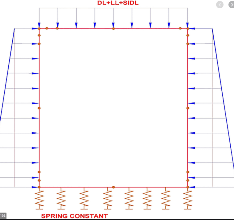
When analyzing a box culvert I know the trend is to apply an equal but opposite upwards force on the bottom slab to model the reaction of the downwards forces and to place a pin support below the walls. (The assumption is that the soil below provides a uniform reaction force).
For a single cell box culvert, this method gives resulting moments and shears that are virtually identical (within 0.1%) to if you were to place soil springs underneath the bottom slab as the support conditions, and apply no external upwards reaction force.
Such conditions are shown below.
For the single cell culvert with pin supports, the equal but opposite upwards force in a net zero change at the supports, thus there is no reaction.
2_krvyb1.png

1_mdqfpq.png


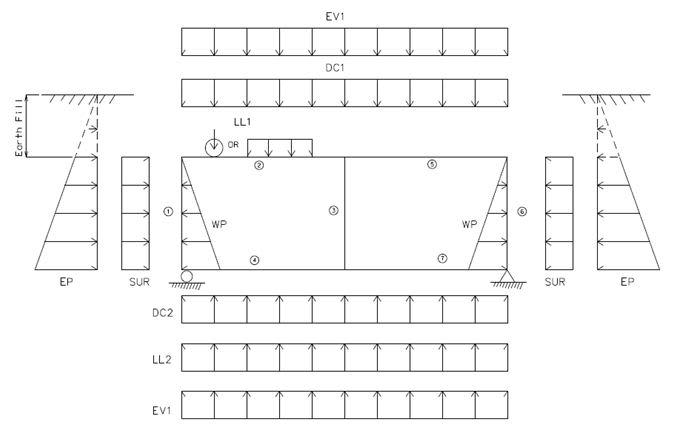
My question is how to go about this approach when modelling a double cell box culvert. If doing the method where an equal but opposite reaction is applied, is a pin support placed below the middle wall? or is it left out like shown below.
3_fajru6.jpg


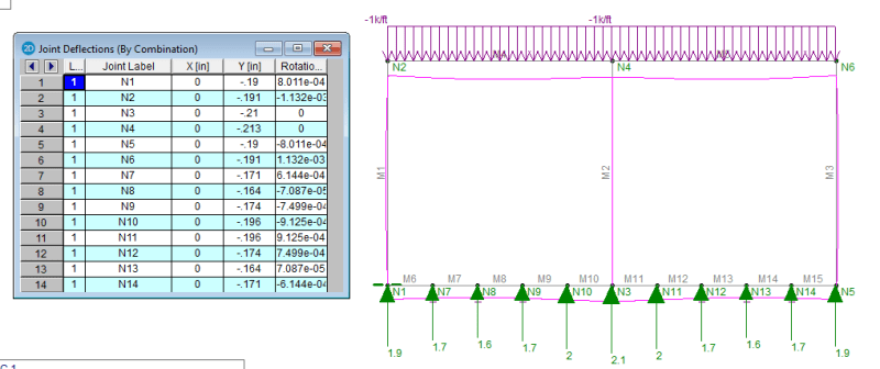
If a pin support support is placed below the middle wall it results in forces at the pin support (i.e. no net zero support forces), and moments and shears that are slightly different (5-10%) from that of a model that uses soil spring supports. See reactions below for supports below each wall.

4_cobzvf.png


If the middle pin support is not placed in the model, then the resulting moments and shears match up closer to that of the soil spring support condition.
Which method is the most realistic representation of the forces? A pin support under all three walls, under exterior wall only, or using soil springs?
I would think that by having a support under all three walls and getting different reaction forces, it isn't modelling it as accurately as it should be, since this no longer results in the assumption that the soil gives a uniform reaction force.

Thanks.
 
Replies continue below

Recommended for you

I have no idea what the trend is, but I can see no reason to simplify any further than using spring supports to model the soil. For arch culverts I model both the foundations and the fill around the arch with plate elements, and that would be my preference for box culverts as well.

Doug Jenkins
Interactive Design Services
 
If you like to perform calculation by hand, I suggest to use moment distribution (Hardy Cross) method. Otherwise, use computer model with spring supports is the way to go.
 
If you analyze a box culvert by applying an equal but opposite upwards force on the bottom slab to model the reaction of the downwards forces , you do not need a pin support at one side and a roller support on the other side if you perform hand calculation .

However , the structural analysis softwares so stupid that , giving UNSTABLE MODEL alarm if you don't provide two supports.. so, pin supports are provided to cheat the software.

For two or more cell box culverts, you are expected to provide only two fictious supports at far ends to keep the model is stable..
Another alternative, the use of springs WINKLER MODEL.

When I was a young engineer, we were using slide rules and performing hand calculations and I remember the saying of these years
regarding Computers,

 
However , the structural analysis softwares so stupid that , giving UNSTABLE MODEL alarm if you don't provide two supports.. so, pin supports are provided to cheat the software.

Agreed.
 
I think the reason that some people do the opposite reaction is because it produces forces in the bottom slab that are slightly more conservative, while slightly reducing top slab forces.
The largest difference in forces in noticed under self weight, as the assumption is that the weight of the walls is equally distributed to the soil as an upwards reaction. This results in large forces at the pin supports (if all three walls are pinned). But I don't feel this models it quite correctly. I think that by getting a reaction in the added pin supports (for model stability) that it changes your assumption as you now have an addition resistance under the walls, therefore the soil reaction is no longer equally distributed.

I suppose another way to view it is to look at it sideways, where the vertical forces are now applied as equal and opposite horizontal reactions. By doing this, it can be seen that there shouldn't be additional reactions at supports in this direction, and all elements will be equal and opposite.
 
The most appropriate and accurate method is the beam on elastic foundation (spring) model, that take into account of settlement and deflection.
 
Good question!

Quade999 said:
If the middle pin support is not placed in the model, then the resulting moments and shears match up closer to that of the soil spring support condition.

I may be wrong but my guess for the reason that the soil spring model behaves more similarly to the 2 support condition is because you are using very soft soil springs. I would venture to guess that as you increase the soil spring stiffness, you will begin to see that the soil spring model will tend to agree more closely with the model where you have 3 supports. What spring constant are you using? What is the maximum displacement of the spring? Is it realistic? For reference, I may use anywhere from 2 to 4 ksf/in as my spring constant but I typically glean advice from the geotech engineer on the job.

I would tend to agree that the soil spring model is the most accurate (and actually easiest for you to model in the computer) but you need to make sure you are using proper modulus of subgrade reaction values. In the past, when I have modeled this using supports, I do actually place a support beneath the middle culvert wall.

I also can't help but notice that you are using MIDAS Civil. I too use that program to model culverts.
 
The springs I varied between 2.5 ksf/in to 8 ksf/in based on information provided by the Geotechnical Engineers. The difference between the two values is about 1% at most, so they both line up pretty well with the 2 support condition.

I am also using area springs in the model, as opposed to point springs at nodes. This way it creates a more uniform shear and moment diagram in the bottom slab as opposed to one that is jogged.
 
Interesting. That is news to me. Next box culvert I design, I will have to play around with the different models as I typically either model the soil springs or the 3 support condition. Thanks for the info.
 
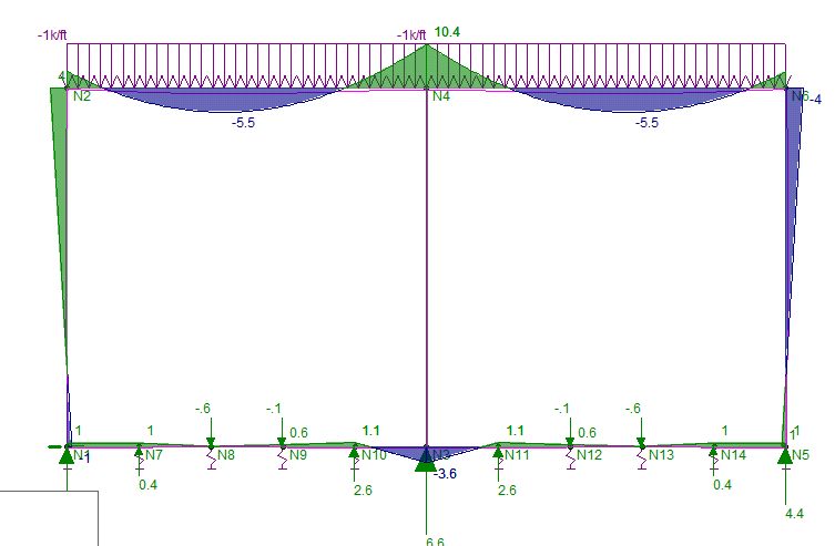
Below is a 2 cells (2-10x10) box culvert model I ran. Each support node has a spring with k = 10k/in. For simplicity, only the roof is loaded with 1 klf uniform load. FRom this model, I got everything need for design.

image_n9a2kf.png


image_n5ldq1.png
 
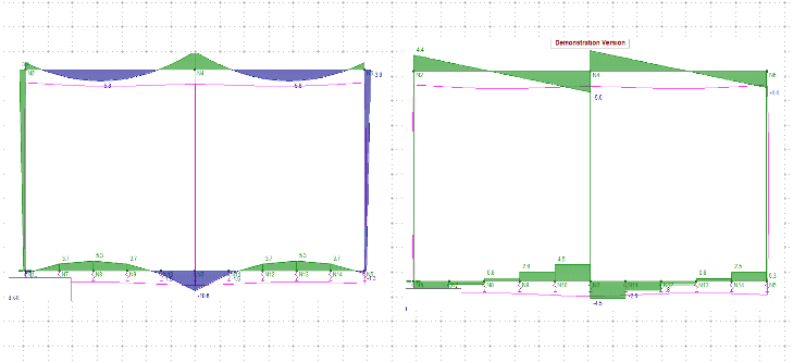
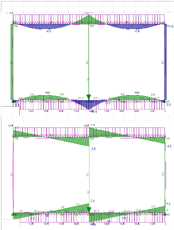
Below is the comparison between area springs (first picture) and the equivalent point springs (second picture). For moment in the bottom slab, there is virtually no difference in results between the two methods, but for shear you can see that the point springs will underestimate the shear in the bottom slab. I suppose this difference could be minimized by just adding more nodes and more point springs.


1_tovqlu.png

2_xqmwg5.png
 
The small difference is no big deal. I've never thought of it, what is the advantage of your method? Just curios.
 
Quade999 said:
I suppose this difference could be minimized by just adding more nodes and more point springs.

Exactly, divide the last slab elements adjacent to the wall elements up and you should see the results converge.

In addition, based on your later post, you should create a node that corresponds with the edge of the haunch which is where you should be analyzing your shear
 
I think you mean dv from the edge of the haunch?
Moment would be at edge of the haunch.
 
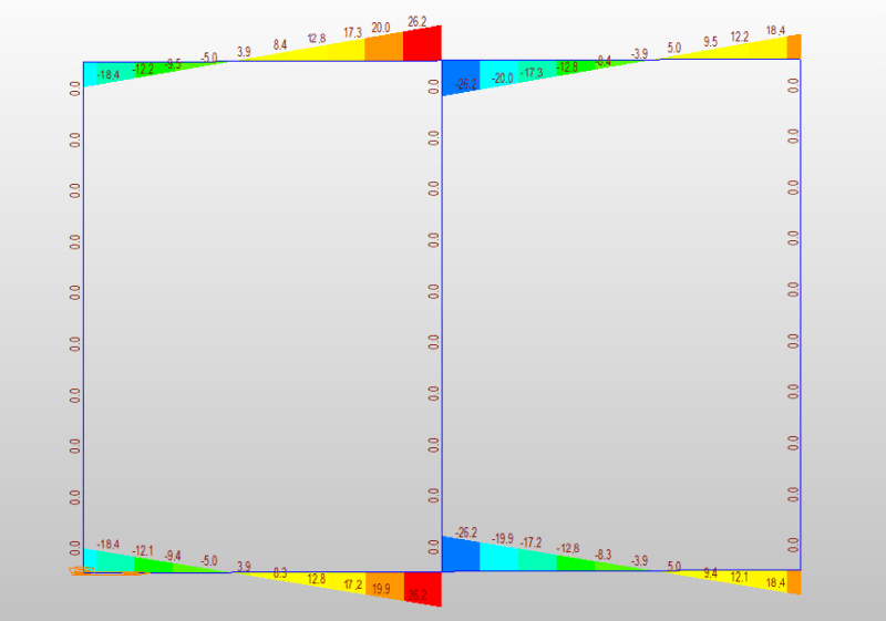
Results below is to demonstrate effects of the change of spring constant from 10 k/in to 1000 k/in. This has been the reason I prefer the elastic spring model, if the spring constant is available, and realistically represents the characteristic of onsite soil.

image_ceyf9w.png
 
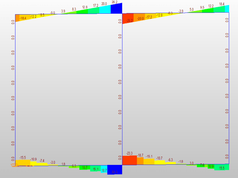
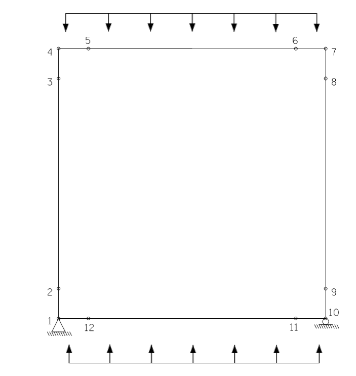
This is a model with pinned supports and uniform load at the base.

image_usm8fo.png


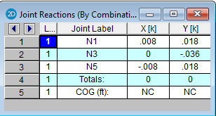
Here is support reactions.
image_ogmzyx.png
 
Status
Not open for further replies.

Part and Inventory Search

Sponsor