Continue to Site

Eng-Tips is the largest engineering community on the Internet

Intelligent Work Forums for Engineering Professionals

  • Congratulations IDS on being selected by the Eng-Tips community for having the most helpful posts in the forums last week. Way to Go!

Double end studs with reduced shank 1

Status
Not open for further replies.

Vitalis 1977

Mechanical
Jul 26, 2019
6
Hi guys,
Could somebody assist me on the following queries?
Double end studs with reduced shank according to DIN 2510 have been specified for the bolting connections of a vessel's nozzles.
Design temperature for this vessel is 450 deg.C and Pdesign = 25 barg.
1)Why use these types of studs instead of typical stud-bolts or even bolts? Is it because of the elevated temperature?
2)What is the purpose of the extended parts (marked in attachment) of the threaded ends.
3)How can I calculate bolt lengths for various flanged connections.
Thank you all in advance.
 
 https://files.engineering.com/getfile.aspx?folder=65f02497-b2d3-429d-a57c-d90fa842d1c0&file=th.jpg
Replies continue below

Recommended for you

Vitalis 1977
Is there a specific shape to the " extended parts (marked in attachment)"?

Sometimes its possible to do all the right things and still get bad results
 
Looks like maybe wrench flats, I'd think the reduced shank is for fatigue resistance, don't know about any of the rest.

Regards,

Mike

The problem with sloppy work is that the supply FAR EXCEEDS the demand
 
looks like a turn-buckle body to me.


another day in paradise, or is paradise one day closer ?
 
that looks like "in casing" turbine studs.

the right end should have a slight taper face that matches the bottom of the drilled blind hole and the end flat. the extension with no threads is to keep the studs threads in the good section of blind threads in the casing. a common practice when installing these was to add a cardboard disk so the stud would not be in direct metal to metal contact when screwed to the bottom.

the left end should be wrench flats for installing and more so when trying to remove.

one reason for the reduced body was for ultrasonic NDE, if full body the threads would prevent "seeing" the outer diameter of a full body. the flat surface on the other end was to provide reflection for NDE
 
There should be a suffix after DIN 2510 and material spec probably . There are many "form" variations, and material options for some pretty specific temperature ranges available.

 
I believe those are torque to yield studs. The reduced shank is so this part of the stud can be stretched to yield without over-stressing the threaded portion. The head extensions have wrench flats on one end to allow the stud to be tightened into a threaded hole (like in an engine block). The other end seems to have no flats and would be a pilot to allow the stud to enter the threaded hole easily.
 
Flats allow driving the other end into a blind tapped hole, then the exposed end must? go to a nut.

Reduced diameter shank limits stress in the threaded portions.

another day in paradise, or is paradise one day closer ?
 
But for piping (nozzle) connections? I don't get it...

The problem with sloppy work is that the supply FAR EXCEEDS the demand
 
Hi this link should help
“Do not worry about your problems with mathematics, I assure you mine are far greater.” Albert Einstein
 
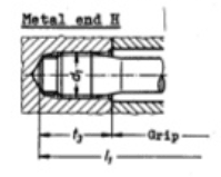
The near end (nut end) of the stud in the OP picture appears to have type R or type S wrenching flats, and the far end (bolt end) appears to have a type H (118deg) coned bearing face. As byrdj noted above, the type H coned bearing face is intended to seat against the bottom of a tap drilled blind hole. DIN 2510 part 1 covers various applications/installations using these studs, and DIN 2510 part 8 covers threaded holes for your type H stud end.

din2510_form_h_qegnyf.png
 
Status
Not open for further replies.

Part and Inventory Search

Sponsor