Continue to Site

Eng-Tips is the largest engineering community on the Internet

Intelligent Work Forums for Engineering Professionals

  • Congratulations pierreick on being selected by the Eng-Tips community for having the most helpful posts in the forums last week. Way to Go!

Doubt About Center of Rotation

Status
Not open for further replies.

Yt.

Structural
Mar 10, 2015
100
Hi
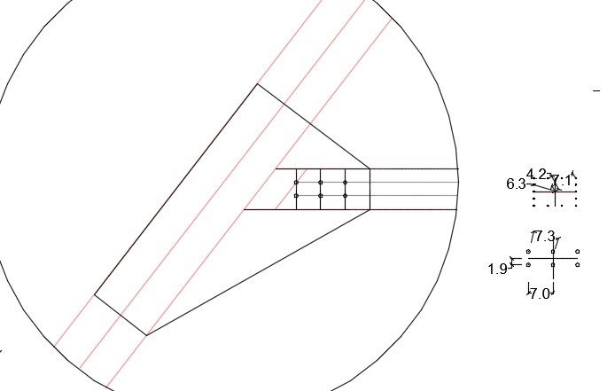
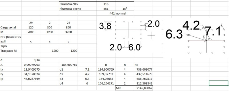
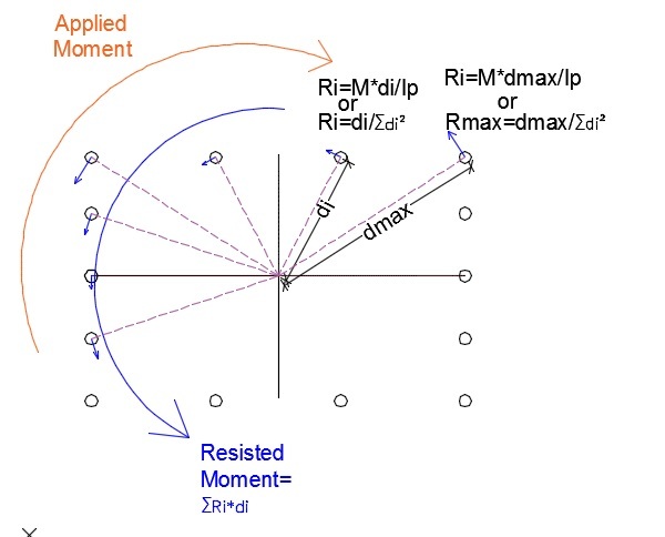
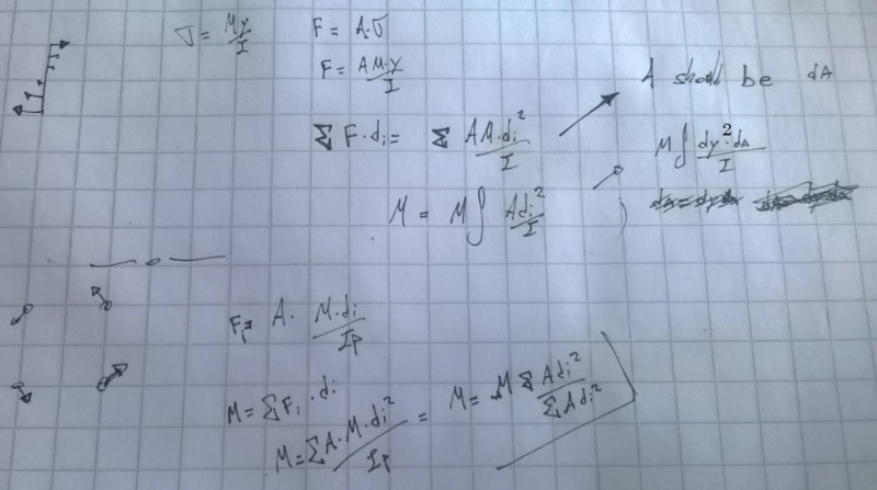
I been working with the center of rotation to estimate the reaction on bolts groups with the expression Ri=M*di/Ip. Where M:Moment, di: distance from center to bolt and Ip: Polar Inertia.
Ip=Ix+Iy
Ix=summation(A*dyi^2)
Iy=summation(A*dxi^2); (Parallel axes Inertia, but ignoring bolt inertia for being small)

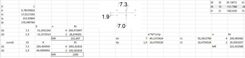
My doubt begins while trying to match the acting moment with the resisted moment by the group by using the following

Resisted Moment= summation(Ri*di)

My reactions are pretty smalls and the resisted moment is also small. But makes no sense with the applied moment.

I also tried to decompose the forces by axis thinking that i had a confusion when measuring the distance directly from the center of rotation to each bolt center.

There is another approach which takes reactions as follows:

Ri=M*di/summation(di^2)

This method obviously match the applied with the Resisted moment, but i think that this method is just an extension of the Resisted Moment expression stated before.

Am I getting it wrong? is it Ok to have relative small reaction because the Ip? Any guide?
Thanks
 
Replies continue below

Recommended for you

Hi

It would be helpful if you posted a sketch of the situation but from your description I can't help you.

“Do not worry about your problems with mathematics, I assure you mine are far greater.” Albert Einstein
 
Ok, i'll sketch it later today
 
When working with a bolt group, you assume the "area" of each bolt is 1, without units. Hence, the polar moment of inertia of a bolt group has the units "in^3," not "in^4" like you normally get with a moment of inertia.

So, your approach is correct. For each bolt, multiply one by the square of its distance from the centroid of the bolt group. Repeat the process for the y direction. Add the two valued together, and you have the polar moment of inertia.

To determine the force in a given bolt, you multiply the moment about the entire bolt group by the distance of the bolt in the x direction from the centroid of the bolt group, and divide by the polar moment of inertia. This is the x component of the force, due to moment (you must add on any x force due to direct load). Repeat the process for the y direction. The force in the bolt is the square root of the sum of the squares.

DaveAtkins
 
Thanks Dave, but considering A euals 1 means that i'm only working with the second approach.

I came here yesterday to post the skecth but the server was under maintenance.

This is my case but i'm working with SI units. M: 1200 kgf*cm; so measuares are in cm. The excel are the calculations and the Resistet moment is MR (Momento Resistido)

I'd try 2 schemes one with nails and another with bolts. The Nail pattern has a greater Moment reaction than the applied, but i don't want to push really hard against normal fiber of my wood member (Just for precaution, i know how to control splitting).

Then when i tried the bolt group the Resisted moment was critically low and the approach begins to seems strange to me.
This are my members:
Members_kf6y1a.jpg

This are the results
for nails-
RNails_mldumc.jpg

For bolts-
RBolts_wgq14n.jpg

And the scheme of reactions-
Scheme_ei1tye.jpg


Both approaches are widely used today (Example, AICI and Australian wood code) but the results are differents. Even when those are trying to explain the same response.

The Ri=di/summation(di^2) has it's origin on glued members, while i don't know where the Ri=M*di/Ip method came from but it's similar to beams equilibrium. Non of the methods consider any deformations of the members or the fasteners, any way both should be conservative(¿er?) than an instantaneous center of rotation.
 
I forgot to including M in the Ri=M*di/summation(di^2); But I do included it at the excel equations.
 
Hi Ytyus

I fail to understand why you are calculating Ix, Iy, Iz, I must be missing something, however have a look at this site it offers a solution similar to that of method 2 you posted.

Look for shear on bolts caused be torsion


“Do not worry about your problems with mathematics, I assure you mine are far greater.” Albert Einstein
 
Just a hint. Check this book. They derive the formulas for moment resistent rigid and semi rigid connections with bolt-like connectors.

Structural Timber Design to Eurocode 5 by Jack Porteous, Abdy Kermani.

I always use Ri=M*di/summation(di^2) to design connectors.
 
Thanks for the answers, after arranged my doubt i solved it. My mistake was to consider that the first method was retriving me a force, instead this returns shear stress applied on the fasteners. So the force should be Ri=A*M*di/Ip; Then M=Ri*di match the acting moment.

solved_gaudri.jpg
 
Hey, the documents both given to me are really cool, thanks!
 
Status
Not open for further replies.

Part and Inventory Search

Sponsor