Eng-Tips is the largest engineering community on the Internet

Intelligent Work Forums for Engineering Professionals

Downhill Pipeline Back-Pressure Control 3

Status
Not open for further replies.

Mike4chemic

Chemical
Oct 9, 2004
71
0
0
IL
Hello,
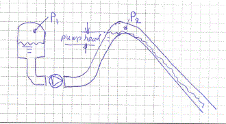
I am involved in the design of 8" geothermal condensate pipeline, its function to transfer the hot geothermal condensate from the Plant to an injection well. Since the condensate is at the saturation conditions( 5 barg& 159 deg.C),there is a pump station, which increases the condensate pressure to overcome friction and elevation losses and thus allows to avoid condensate flashing and possible two-phase flow problems like a slug flow. The pipe consists of two sections: upward (elevation 20 m) and downward section (-60m).See the attached sketch
In order to keep the pressure at the upper point of the pipe, we intend to install at the pipe low point an automatic back-pressure control valve, which will keep the condensate pressure at the pipe's high point above the saturation pressure.

Is it feasible to perform this control,given the fact that the length of the downheel pipeline section is 2 km?

Thank in advance, Mike
 
 https://files.engineering.com/getfile.aspx?folder=fc37cc64-0093-441a-b856-a9494054e34d&file=ENG.pdf
Replies continue below

Recommended for you

Yes, but I would also add a pressure control immeadiately upstream of your control valve to maintain 5 bar there also. Depending on your pressure drop you could get 5 bar a the high point, but less than this at the arrival point.

You really need to plot the profile against the hydrostatic head of the pipeline at various flow rates to work this out properly. Where is the high point along the line? Exactly in the middle?

Also to avoid flashing fluid at the top your stopping flow needs to be quite slow and undertaken by ramping the control valve closed and then continuing to pump until you hit max pump head / no flow limits.

Another, though more basic option is to set the back pressure at the end point equivalent to the high point plus 5 bar, so basically 11 bar. This might mean you need a bigger / higher head pump, but it's pretty bullet proof for all flows from 0 to full flow.

what happens in the well? At 2 bar it'll flash off pretty fast.

Remember - More details = better answers
Also: If you get a response it's polite to respond to it.
 
Agreed, you also must prevent flashing of this condensate just before the backpressure valve when the line is at max. flow.

This may not be as straightforward as it may seem. Running pressure control on a liquid line with 2 control valves interacting can be difficult, especially with erratic inflows at the condensate collection vessel. Liquid is incompressible, line pressures may transiently collapse with the LCV and PCV chasing each other, and you may get line hammer as vapor implodes also. Find a way to do this with only one control valve inline. Perhaps LIC cascade onto pump speed via VFD (no LCV) at the booster pump and the current PIC / PCV. Check that the VFD enables a wide speed range to cater for flows down to minimum. In a single valve arrangement with no LCV, pressure just upstream of backpressure PCV would also have to just above 5barg to prevent liquid siphoning out of the vessel without the pump running. So in this case, check which of 2 criteria is controlling and configure controls to suit.
 
Gentlemen,
Thank you for the useful recommendations (I gave you two stars).
Assuming, we will implement the control logic, as you suggested, including the pump's VFD control.
Based on your experience, How practical it is to keep the more than 2,000 m pipeline pressurized, without
hammering phenomena ? Or we have to design in advance the pipeline with the bigger supports, to mitigate the pipe "jumping" (might be very expensive)?
Are there any special design requirements for the pressure control valve, in terms of reaction time, turn-down ratio , type of valve, electrical or pneumatic actuator?

Thank you again, Mike
 
Can you add an expansion tank (or a condensate tank with air/nitrogen pressure blanket) at the high point? At the low point? The extra volume of cooler water (even at saturated pressure and temperature in the pipe itself) will add a mass effect (flywheel effect) that will help slow flashing and surging near the control valve.
 
Hi Mike

I assume is not steam condensate, but separated geothermal water/brine. Not a new problem in geothermal power plant. Quite common to have to pump saturated hot reinjection water over a hill.

One solution is to not worry about the back pressure downstream of the pumps. Just leave the reinjection well open. There will then be two phase flow (channel) down to the reinjection well. The pressure over the hill with match the saturation temperature of the water. The pump will just be lifting the water to the top of the hill.

Most reinjection stations would use VSDs.


If you can implement VFD without this inline LCV, there is no reason for line hammer due to transient pressure collapse / subsequent vapor implosion. Agreed, you may still need to ensure liquid line hammer due to sudden closure of the downstream PCV may be possible. This can only be due to
a)loss of level in the flash vessel (add LSLL at flash vessel). Also check that you have sufficent control volume ( between LAH and LAL) at the source flash vessel so that pump speed variations are slow even when flash drum inflow is erratic.
b)pump trip (use slow closing pump check valve)
c)high speed closing of PCV (include DCS ramp down rate limiter). Additional protection measure may be a small reserve instrument air bottle at the PCV ( with backflow prevention check valve).

With these control and protection schemes installed, there would only be a low risk of liquid line hammer, for which you could take credit for the 1.3x factor in B31.3 for such rare events; i.e max generated line hammer pressure = 1.3x line design pressure.
 
Mike,

A lot of the issues here are not known to us.

The key to this is whether you want to keep the liquid as a liquid - sounds good to me, but in reality it really creates some noise and more backpressure as the liquid goes from single phase to two phase.

The speed of response of the various components is the key here. If you can slow down the actions of the valves or pumps which control flow (your LCV or VFD)and speed up the reaction of your end pressure controller than you should be able to maintain pressure> 5 bar at any point. however the volume is small and to be sure you probably need some sort of pressure accumulator or jockey pump to maintain pressure it if drops below 5 bar. At no flow you will also need isolation valves as control valves have a tendency over time not to seal shut.

It sounds like this is really a long pipe if you're talking about supports. Pipelines are usually buried and avoids this issue.

Thinking a bit more, your midpoint PT is not really needed. Just fix the end pressure to 11 bar. Assuming your pressure drop for friction is pretty low (2 bar max?) then adding a midpoint pressure TX is going to make about 1 bar difference. Just save the money on the transmitter cabling etc and fit one at the end.

Nothing particularly special about the PCV. Pneumatic controls are very common, but electric would work also.

George has it explained well.

For this design where pressure doesn't change much with flow as most of the pump pressure is head, then using a fixed speed pump and a level control valve would work equally well IMO.


Remember - More details = better answers
Also: If you get a response it's polite to respond to it.
 
I have never implemented a system like you describe, so keep in mind that my comments are based on theory and first principles.

You cannot maintain 5 barg at the high point unless the pump is running. This means that the pump must run continuously whether the operation is continuous or not. I like the idea of using a VFD for the pump and a single control valve as suggested by George, but I would use the pump speed to control the pressure at the high point.

I would use the valve at the end of the line to control the flash tank level. If the LCV is positioned as per your sketch, when it closed there would be an awful lot of liquid with a lot of momentum downstream of the valve and this could cause problems with cavitation.

I don't like the idea of a second PCV at the end to prevent flashing there. Rather select the set point for the high point pressure and size the downleg pipe diameter so that flashing will not occur in the downleg under the expected range of flow rates.

Katmar Software - AioFlo Pipe Hydraulics

"An undefined problem has an infinite number of solutions"
 
katmars got a good point, but I would use the pump to maintain pressure just upstream of the control valve at the end of the pipe.

At the end of the day, if the pressure drops below the saturation pressure the pipe should be OK, just don't do it regularly and re-start slowly by raising the pressure and then sweeping out the two phase stuff slowly, but not too slowly ( so about 1m/sec).

Remember - More details = better answers
Also: If you get a response it's polite to respond to it.
 
I don't think it makes a big difference whether the pressure is controlled at the high point or the end point. Either way, the pressure at the other point will be maintained by correct pipe sizing.

But from a practical point of view, grouping all the controls at the end of the line might be better. There could be savings by using a single signal cable or a single telemetry station, a single point for inspection and maintenance etc.

Katmar Software - AioFlo Pipe Hydraulics

"An undefined problem has an infinite number of solutions"
 
We have designed a number of these geothermal reinjection systems. The largest is DN750 and 7km long.

We do not bother to control the pressure downstream of the pump. The flow is channel flow from the top of the hill to the reinjection well. The steam pressure in the space above the water matches the saturation temperature of the water. See sketch below. If there is no thermal loss P1 = P2. but there is some thermal loss and P2 will be less than P1. There will be some water flash to steam.

Important to avoid upset conditions that would collapse the steam space above the water. If the pressure is controlled down stream of the pump, the steam space can still form during start up and shut down.

Capture_exoqwz.gif
 
I thank you all.

Kevin,
Assuming the thermal losses through the uphill section is 2 deg.C, the P2 (vapor pressure) can't be lower than 4.7 barg.
But on the other hand,the P2 is set by: the downstream re-injection pressure + two-phase fluid friction losses through the downward pipeline - elevation head gain.
In my case, assuming P2=4.7 barg and required re-injection pressure is 1 barg, the available pressure drop(driving force) is about 3.7 bard(not including the elevation gain of 60m).
As far as I understand,the available pressure drop need to be equal to frictional pressure losses in the line , otherwise P2 will drop below 4.7 barg.
Is't feasible?

Thanks, Mike

 
Status
Not open for further replies.
Back
Top