Continue to Site

Eng-Tips is the largest engineering community on the Internet

Intelligent Work Forums for Engineering Professionals

  • Congratulations KootK on being selected by the Eng-Tips community for having the most helpful posts in the forums last week. Way to Go!

Downsizing hydraulic cylinder 1

Status
Not open for further replies.

marinovich.91

Marine/Ocean
Jan 7, 2020
11
Hi to everyone, first I wil try to put here my current system, then what I would try to do and then couple of questions. This may be a big thread but my apopogies.

The current problem on my sailboat is that somebody before I bought it had putted hyrdaulic steering on 31 foot boat, and made couple of mistakes along the way.

So courrent setup is that i have:
28cc/turn steering helm pum connected to 70cm diameter steering wheel - axial piston pump
168cc capacity steering hydraulic cylnder
System max press 70bar

This gives me 6 turns from end to end, and main problem is that I dont feel the rudder at all(no feedback). I have been googling it a lot and found that there is couple of solutions.

Before I continiue I must mention that I have raymarine EV100 Autopilot connceted to my steering wheel over Autopilot wheel attached to it(with small electromotor)


So to get any feedback from rudder I found that I need to remove checkball’s from nonreturn valve system on helm pump(80% sure). So fluid from my steering cylnder can influence steering wheel.


At current system I dont need use any effort to turn the wheel and when there is rough sea, sailboat is behaveing like local drunk, since I cant chatch the boat>>There is no feeling and 6. turns from end to end.
Manovering is story for its own.

Solution for this is downsizing hydraulic cylinder or buying bigger capacity pump. Since I dont have space, and hy. cylnder is cheaper to change I decided to change the cylnder.

The main problem arise when I contacted Seastar tech. support about it.
He told me downsizeing the cylnder effort on steering wheel incrises a lot. (a lot is the main problem).

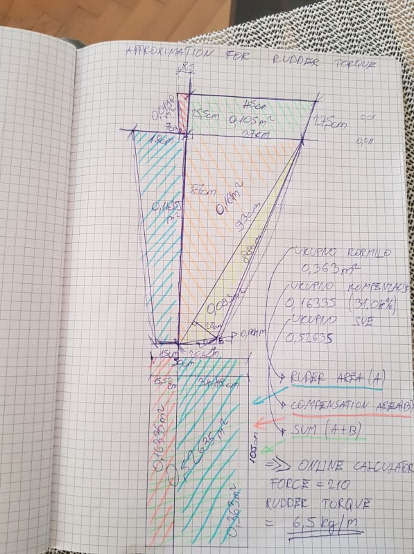
Recently I calculated my rudder torque by calculateing area an running it in calculator and got 6kg/m. Pictures attached, Calculator web site is on this link..

Calculator gave me:
Force of 210
Rudder torque of 6kg/m

I am not sure since there isnt any units; what this should mean

Solution 1.
I would like to go for 69cm3 (2.5 turns) capacity of hydraulic cylnder but I dont know if my autopilot will be able to handle it becouse friction of fluids and pump. As well max torque of cylnder is 32 kg/m but output force is 170kg.


Solution 2.
Another option is to go for 84cm3 (3 turns) capacity of hydraulic cylnder but I dont know if my autopilot will be able to handle it becouse friction of fluids and pump. As well max torque of cylnder is 58 kg/m but output force is 387 kg.

Lady in Hydrodrive told me:
On application 28cc pump and 84cm3 cylinder, on shaft pump, to reach the max pressure, needed a torque of 42 Nm on pump shaft.What does this mean if my max torque from rudder is 6kg/m?

But I want the feedback as well.

The main question is how to calculate how much stiff my steering wheel is going to be, since I want it to be just on border so my autopilot can handle it, to have feedback, as little as possible turns and normal effort steering.

Thank you for your Help and time

 
Replies continue below

Recommended for you

I wrote in the thread that I am considering to remove them, to get force feedback, at high speeds (max 7 knots) esspecially when sailing. [smile] It is ok to use rudder angle metter when sea is calm and quiet but ar rough sea you need as much feedback as possible to mentain direction esspecialy when sailing, you must hold the boat on line in between uncontroled and controled sailing(let say like this but it is profesion of its own.
My whole system works at maximum of 70bar.

"Lady in Hydrodrive told me:
On application 28cc pump and 84cm3 cylinder, on shaft pump, to reach the max pressure,torque needed is 42 Nm on pump shaft.What does this mean if my max torque from rudder is 6kg/m?"

Cylnder in question has 58kg torque at max pressure of 70bar and Force of cca 386 kg.

52/6 =866% or 8.6 times
4.2kg at 1m is at(70cm radius/2 = 35cm) comes to 12kg/35cm
12kg/8.6 = 1.4kg (70cm radius/2 = 35cm) at maximum of 35 degrees and speed of 7knots

1.4kg is needed in istance* (at maximum) when you go full left or right on full speed of 7knots to turn the rudder 35degrees
Is this right way to look at this solution?
By your opinion I will get force feedback for sure if I remove nonreturn valves?

Istance / since speed drops when boat starts to stear thus lovering rudder resistance trough water.
 
@Compositepro, It's normal to put a pair of pilot operated check valves in the working lines of a helm pump - I think the problem here is that the OP has omitted the pilot lines from the drawing (they are routed to the pump output on the opposite side, and lift their associated check valve to create a return path when the pump is generating pressure in a manner akin to counterbalance valves.

@marinovich.91, Those PO Checks are fitted for safety. They're there to prevent the steering gear from backdriving the helm pump (for instance if the rudder catches a big wave) and breaking your wrist. It might be that your rudder is small enough for that not to be a risk, but in many installations which use pumps like this, that is definitely not the case. I have no experience of using these things on sailing boats, but the total absence of force feedback on the helm is taken for granted in motor vessels.

A.
 
On sailboats you cant find hydraulic stereeng except realy rare cases like mine, Usualy it is well calculated wire rope assembly with force feedback.

It is basicly not possible to stear 7 ton boat as it sailing 7 knots to brake arm or something mentioned since sailing isnt that fast.

As rudder calculation shows only 6kg of force you need at leaver of 1m to go for full steer at maximum speed.

I am just interested what i will get when I do those things, and how to do it right, so I dont lose my autopilot capability.
 
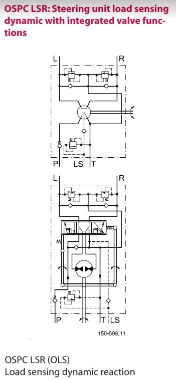
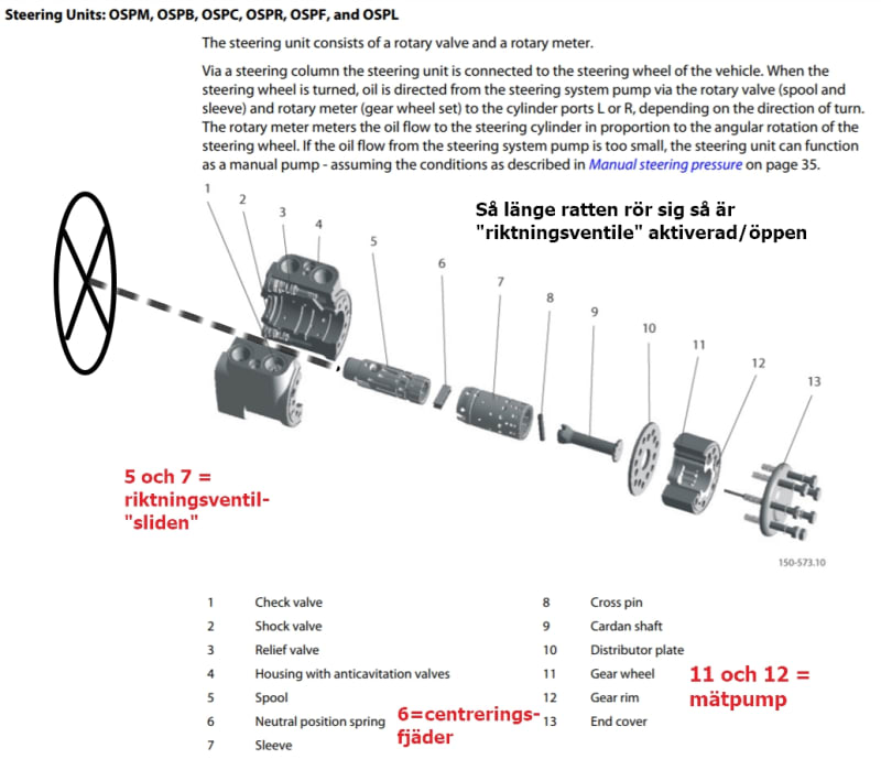
You need an Orbitrol steering unit like this one from Danfoss.
orbitrol_jzfxta.jpg

"Reaction" means that the steering wheel has "hydraulic contact" with the rudder. This valve below is made for a Load Sensing, LS, pump system so it will work with a pressure compensated variable displacement pump. or an LS fixed displacement pump.
OSPC_LSR_Orbitrol_reaction_slhs0t.jpg

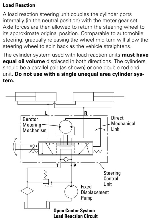
Eaton has their own line that basically works the same way. This one is with "Open Center" and made for a constant flow system pump.
OC_R_recation_eaton_orbitrol_lewiks.jpg


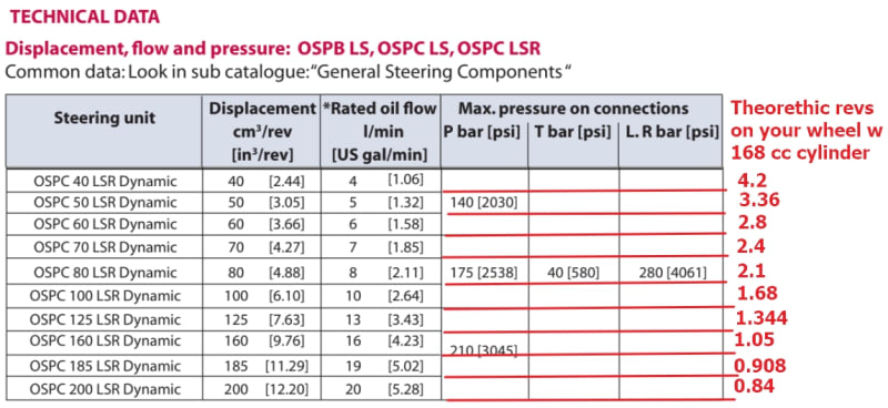
This steering system can also be manageable without a servo power pump. The steering unit has a metering pump built-in and the check valve between P and T on the images allows "emergency steering" which is tough on an articulated heavy front loader but should be an easy one for a rudder on a sailboat. The metering pump size is optional so you can get the right rudder speed contra how many wheel-turns you need for the rudder to go end to end
OSPC_LSR_Orbitrol_displacements_ijppo1.jpg

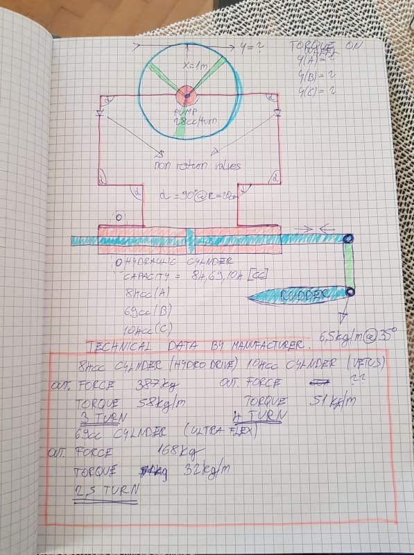
Adding your images as well
Hidraulika_uzbi8w.jpg
Proracun_za_kormilo_qs6ltz.jpg
 
Pump shaft torque T = D*p/20pi
T in Nm
D pump displacement in cc/rev
p pressure in bar
If you know cylinder push rod force and effective cylinder area you can find pressure p. Then you can relate helm force to cylinder force, thence torque to rudder.

Ted
 
@akkamaan Thank you for time and effort, but system looks over complicated.Buying anything except cylnder is too expensive for me. For sure I am going to lok at it, google Danfoss pump as well. But I would rather modify my pump for force feedback( since I can remodify again, if I dont like it) and buy smaller cylnder for turns.
As well I saw that pump delivering press is more than max 70bar which can be resovled with relief valve, but it comes agaim to simplicity of system.


@hydtools

This is exactly what I need but your equation dont work as Hydrodrive support told me.

Please can you explain equation littlw bit more;
D - displacment of the pump in cc/rev =28
p - max pressure in system required to do the action(turn rudder to 35 degrees)??
20 - constant connected to the pump??
pi - 3.14


Since Hydrodrive told me with 28cc pump and 84cc cylnder at max press of 70 bar on pump shaft I will have 42Nm

wit your equation;

T=28*70/(20pi) = 31Nm
If 20 is constant related to the pump and if it is 15 than I get correct answer.

If it is constant can you tell me what is the name of it so I can be sure.

Thanks Ted & akkamaan
 
20 is the result of making the units consistent for Newtons and meters multiplied by the 2 in the rotary term 2*pi. 2*10=20
What are the cylinder rod and piston diameters?
Pressure = force/area; area = piston area - rod area. Force = rod force

Ted
 
I cant find inside diameter but capacity is 84 cc, stroke is 150mm which gives bore of 32 mm >>rod diameter is 14mm.
Area of rod 87.92cm2 - A
Area of bore 200.96 cm2 B
Effective area B-A= 113.04cm2
^^Force = Pressure*area = 70 bar (kg/cm2) * 113.04 cm2 = 7,912.8kg? Max force? But rod is only 14mm??

Something I didnt do right.
Please
 
Marinowitch.91 said:
I cant find inside diameter but capacity is 84 cc, stroke is 150mm which gives bore of 32 mm >>rod diameter is 14mm.
Area of rod 87.92cm2 - A
Area of bore 200.96 cm2 B
Effective area B-A= 113.04cm2
^^Force = Pressure*area = 70 bar (kg/cm2) * 113.04 cm2 = 7,912.8kg? Max force? But rod is only 14mm??

Your math is way off. There is a "buried dog" in your input data. The numbers do not match.
What is your definition of "capacity 84cc"? Where does this number apply to the cylinder?
Measure or estimate the outside diameter of the cylinder. The cylinder tube wall is approx 3-4-5 mm thick depending on bore diameter so subtract 6-8-10 mm from the outside diameter to get an estimated bore diameter. I would guess the bore is 75 mm with that 32 mm rod diameter
 
Annulus area = (D^2 - d^2)*pi/4
Displacement would be annulus area x stroke.

Ted
 
I messe up formulas for are, now I see.. I used 2rpi instead r^2pi

Inside capacity is 84 cm^3, stroke is 150mm which gives bore of 32mm(2r) >>rod diameter is 14mm(2r).
Area of rod 1.5386cm2 - A
Area of bore 8.0384 cm2 B
Effective area B-A= 6.5cm2
^^Force = Pressure*area = 70 bar (kg/cm2) * 6.5 cm2 = 455kg? Now seems ok. They just undersized it by 15% for safety reason perhaps, and advertize it as 387kg.

I was in hurry and messed up big time.

I first made mistake by area formula than writed down it as cm^2 instead of mm^2. Didnt think at all.

So lets get back on pump torque. Still dont understand how to get te info Hydrodrive told me. (42Nm at shaft of pump)
""20 is the result of making the units consistent for Newtons and meters multiplied by the 2 in the rotary term 2*pi. 2*10=20""??
 
Cc*10^-6 = m^3
Bar*10^5 = N/m^2

10^-6 * 10^5 = 10^-1 or 1/10

Ask Hydrodrive how they arrived at their figure.

Ted
 
marinovich.91 said:
It is basicly not possible to stear 7 ton boat as it sailing 7 knots to brake arm or something mentioned since sailing isnt that fast.

I'd be more concerned about the effects of being pooped while running at low speed - on bigger ships, those are the conditions when you're most likely to lift the crossline reliefs.

If you're going to remove the check valves from the pumps, check whether this exposes any leak paths between the two sides of the circuit. If (as I suspect) the valves are pilot-operated, you'll need to find a way of blocking off the pilot drillings.

A.
 
Found the cylinder and did the math...
Bore came out 30 mm with a 14 mm rod and 83 cc displacement volume. Max force as stated 3870N approx 387 kg (394.5 kg to be exact. (Force is measured in Newton, N, so it takes 9.81 N to lift a mass of 1 kilogram, kg. at sea level)
Calculated some other performance numbers too.

For your rudder torque calculations, you need to understand the unit for torque. It is not kg per m "kg/m" as you have on your pictures. Torque is "Force by distance", ie Newton by meter or Nm. if you are more comfortable to use the mass unit kg for the force so be it, but then it has to be "kilogram by meter" or "kgm"
double_rod_cylinder_3_prsiqt.jpg
 
Wow this is extraordinary.Thank you for time, you put into this.

Just to confirm. Is this power needed on pump shaft, not on 1m, on ideal system offcourse?

Than:
Torque (N.m) = 9.5488 x Power (kW) / Speed (RPM)
= 9.5488 x 0.196 / 60 for 1 (rev/sec)
= 23.26 Nm=2.326kgm( * pump effieciency) + friction in hoses due viscosity and bends >>for real systems?

Thus at wheel of 70 cm (diameter)

I will need to use 6.64 kg of push force at wheel.
How much I will need to use if my rudder needs 6kgm of torque and 210 of Force?
As gotten on below picture.


As well this sentance is not clear for me.
"I'd be more concerned about the effects of being pooped while running at low speed - on bigger ships, those are the conditions when you're most likely to lift the crossline reliefs."

On low speeds ruder torque gets smaller so there isn any force on cylnder and thus no feedback.

EDIT:

Something is not clear: How is possible that pump needs less power operateing at higher speeds (5 turns/s) 39W than on lover speeds 1 turn/s which is 196W.


 https://files.engineering.com/getfile.aspx?folder=303f7f6b-1861-41f6-a7da-9f94faef909f&file=Rudder_torque_calculator.jpg
You misread the chart. The low speed is 5sec/rev, .2revs/sec. Not 5revs/sec.

Ted
 
Status
Not open for further replies.

Part and Inventory Search

Sponsor