Continue to Site

Eng-Tips is the largest engineering community on the Internet

Intelligent Work Forums for Engineering Professionals

  • Congratulations KootK on being selected by the Eng-Tips community for having the most helpful posts in the forums last week. Way to Go!

DRAFTING HELP W/ ANGLED SURFACE IN A BASE PLATE 1

Status
Not open for further replies.

BrittToolEngineer

Aerospace
Aug 4, 2016
239
Greetings:

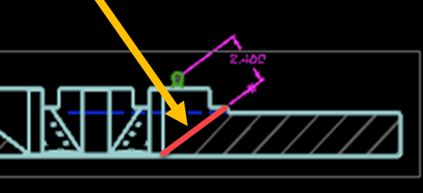
I am drafting a base plate and has (6) angled flats within it. These flats have holes that need called out, which requires a view normal to this surface. I am unable to figure out how to do that with my section view, I think due to it being a section view. Would anyone know if there is a way to create a view normal to this surface with the section view? Attached is a picture.

Thanks,

Brent
 
 https://files.engineering.com/getfile.aspx?folder=8abf1382-d922-45e9-817e-7e9bcc2a9325&file=DRAFTING_HELP.pptx
Replies continue below

Recommended for you

It looks to me like you cannot do it.
I think if you took a section view based off the top view and 90 degrees from Section B-B you will get what you need.

Jerry J.
UGV5-NX1884
 
I would create an intersection curve in Modeling on the flat face at Section B-B. Then use that intersection curve in Drafting as the hinge line for the desired section.
 
You could also create a Point, in your Model, on the Face where you want to View to be centered, draw a Line through the Point, normal to the Face and then create a View looking down along that Line and use this View on your Drawing, Hiding the Point and Line afterwards.

John R. Baker, P.E. (ret)
EX-Product 'Evangelist'
Irvine, CA
Siemens PLM:
UG/NX Museum:

The secret of life is not finding someone to live with
It's finding someone you can't live without
 
Is there a reason why you cannot do a regular projected view from that section view, and use the highlighted line as the "hinge line" ?
What version are you running ?

2020-12-04_14-03-43_h8f5qk.png


Regards,
Tomas
 
Tomas,

The reason we cannot use a projected view is that the angled surfaces do not fall on a quadrant, but angled from a quadrant. I actually did the created the intersection curve as mmauldin suggested, and this allowed me to create a section view facing this surface, thus, allowing me to dimension the holes. Thank you to all for the replies. Much appreciated.

Thanks,

Brent
 
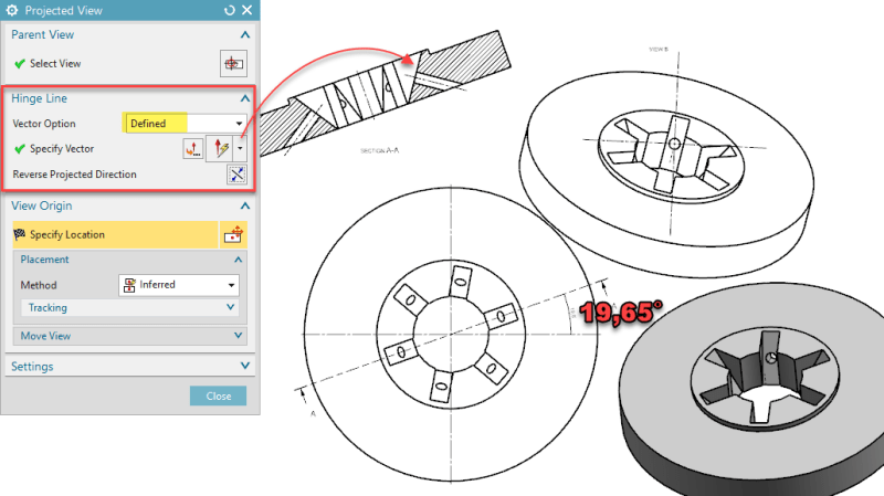
I still do not see the problem, this is exactly what Projected view does/ can do, when you select the ( -the now weirdly named "defined"...)
Hinge line : Vector option = "Defined"
and then select the highlighted line. NX will then use that line as the "rotation axis" for the next view.
The angle of that line does not matter. You can use two points instead of a line for this definition.

Regards,
Tomas
In this example I made the original angle 19,65 ° just to illustrate that the angle doesn't matter for the projected view.

2020-12-09_18-01-30_xostrd.png
 
Status
Not open for further replies.

Part and Inventory Search

Sponsor