Eng-Tips is the largest engineering community on the Internet

Intelligent Work Forums for Engineering Professionals

Drag Strut Internal Stresses

Status
Not open for further replies.

ChorasDen

Structural
Oct 19, 2021
424
4
18
US
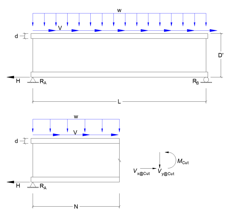
I'm attempting to define the internal shear stresses within a non-rectangular structural drag member and struggling a bit with my understanding of axial forces and how they might affect internal stresses in said member. Take the image below, showing a simple span member resisting an axial eccentric drag load. If we take a cut at a nominal location along the span, 'N', we should be able to determine the internal stresses as a local moment and local shear.

My question comes from the idea of how do I include the axial component loading onto the shear diagram? From the detail below, I have an axial strap load 'H' located at support 'A' taking the accumulated eccentric load overtop the member. My thought is that this 'H' induces a large local shear that is transferred from the web of the member to the flange, and then through the nails/weld of the strap to the LFRS below. I'm struggling to find a good written resource on this concept. Any thoughts?

Base_Drawing_txt55f.png
 
Replies continue below

Recommended for you

First, separate the w and V applied loads and construct separate FBDs for each. The w load case is a simple beam bending condition.

For the V load (assumed distributed load down the length). This load is going to gradually shear down the web, with most of the shear in the last D' length before support A.
The "Vx_cut" is not a shear force, but is an axial force on the section which is the summation of the V load to the right (or H - V*N), BUT it is not uniform thru the beam depth. Similarly, the Mcut is a result of the nonuniform axial load in the beam depth at the section; it is not a pure bending moment in the section.
To get the shear stress in the web, you need to run an FE model, or make some conservative assumptions such as all of the V load induced shear in the web is transferred near the left end.
 
Of course. How else could it work?
However there is an additional eccentric moment and a shear load to that caused by W in the beam and I'm not sure you, or SWComposites, have accounted for it when calculating Ra, nor when totalling M_cut and Vycut that are caused by that shear load.

Mcut = Ra x N - (WN^2)/2 + V x D
Vy_cut = Ra -WN -V x D/N where V is shear in lbs/linear ft, such that H = VxL
Vx_cut = V_lbs/ft ×N_ft -H note this is not V as in shear, it is an axial load in the beam.
It is only horizontal shear in the beam when you consider it as an Axial load as being transferred through the Web to the support. S= (H-V x N)/(N x web_thickness), or Vx_cut/N/web_thickness. I think. (working quickly while making lunch).
Vertical shear Vs is distributed through the Cross section according to VQ/I/t. and M as Sm = Mcut x c/I (both calculated there at the neutral axis)

No FEA required as the right support is a roller, defining the problem as being statically determinate, all axial load must be at the left support.

--Einstein gave the same test to students every year. When asked why he would do something like that, "Because the answers had changed."
 
as above ... superposition. It is an unusual, having axial load in the beam ... so an axial load to combine with the bending from transverse shear, and also web shears to combine with the web shear from the transverse loading.

If you want to "kill it with analysis" you could consider the axial reaction as a shear lag problem

"Hoffen wir mal, dass alles gut geht !"
General Paulus, Nov 1942, outside Stalingrad after the launch of Operation Uranus.
 
Suppose as most questions on here go, I should provide additional context. Assume the 'H' load occurs at a discrete point, and is not spread across the bottom of this structural member, which is what's shown on the detail above. As the distance 'N' approaches zero, does a value for Vx, as a component of the total shear in member V, exist? Intuitively, I believe that it does, but standard mechanics might argue that Vx does not exist, and instead, it's resolved in the bending moment at the cut location.

My end goal is to define the shear in the web of the member, and I'm trying to tease out if the shear at support 'A' is high do the restraint from force 'H', or if the shear is relatively little, due only to the vertical loading, and some other consideration helps to resolve the axial component of the loading.
 
No. Assume like you have already done above. The distributed V load on the top flange occurs at a discrete point, x=N
In which case the axial force to the left of N = H, to the right of N =0.

If you put it at the bottom, most of that load will stay in the one bottom flange and Axial stress in that flange would be H/Wf/Tf at every point left of N.

--Einstein gave the same test to students every year. When asked why he would do something like that, "Because the answers had changed."
 
@ChorasDen I would think the bottom flange is is pretty rigid axially and if you took a horizontal cut just above the bottom flange would see a horizontal shear force that is distributed along the length not really a discrete location relative to the web. To me it seems like the web itself is like a little shear wall with uniform shear support at its bottom, and the bottom flange is like a tension member with a distributed tension force and a point reaction. Starting to think the FEA solution could shed quite a bit of light on this matter.
 
There is no separate Vx "shear" on the section cut. There is a non uniform distribution of axial (sideways) force on the section cut. The "Vx shear" that you are thinking of is the same as the Vy shear.
 
I agree, as the axial stress is not a shearing stress.

--Einstein gave the same test to students every year. When asked why he would do something like that, "Because the answers had changed."
 
SWComp said:
The "Vx shear" that you are thinking of is the same as the Vy shear.

I agree, shear is a scalar component, and thus, doesn't have an orientation necessarily. I was more using Vx & Vy to try and defined the total shear value, V, split between the axial component (x) and the vertical gravity load component (y).
 
Not correct. Axial = F/A only in the axial direction. Shear has orientation. Shear_NA = VQ/I/t and occurs in the horizontal and vertical x,y axes (in the plane of the web)

--Einstein gave the same test to students every year. When asked why he would do something like that, "Because the answers had changed."
 
1503 said:
axial stress is not a shearing load.

I think this is the crux of my question. Why is the axial load not a shearing load? If I have a discrete rectangular section as shown below, this appears to show a shear load in the element. How is this different than an offset axial diaphragm load at the top of the w-section, and a horizontal restraint (strap, weld, etc.) at the bottom bearing location?
shear_element_w2p5p5.png
 
1504 said:
Mcut = Ra x N - (WN^2)/2 + V x D
Vy_cut = Ra -WN -V x D/N where V is shear in lbs/linear ft, such that H = VxL
Vx_cut = V_lbs/ft ×N_ft -H note this is not V as in shear, it is an axial load in the beam.

I missed this response originally, this is what I have come up with myself, just written a bit different. Most written text does not address the concept of eccentric axial loading onto a member, particularly as it relates to non-rectangular shapes.
 
When calculating total axial stress on a small element, axial stress, total stress at the top of the element = F/A +Sv and on the bottom of the element it is F/A -Sv
Sides of the element stress is +Sv on one side and -Sv on the other.
Right. In my field, Pipe stress does not have rectangular sections.

See "Mohr's circle"
Axial stress is not a shearing load because it is unidirectional stress, only in the axial direction, unless it is eccentric, then some shear from the additional eccentric moment is created.
Mohr's circle results in the angle and value of the maximum shear stress.

--Einstein gave the same test to students every year. When asked why he would do something like that, "Because the answers had changed."
 
You can see from your sketch it does in fact cause some shear stress. The shear stress is calculate by VQ/It. If we ignore completely the w component from your sketch, you will find the shear diagram for the beam is uniform, and equal to your drag force V times the beam depth D over the beam length L. This assumes plane sections remain plane, which I guess may not always be true in these cases.
 
Status
Not open for further replies.
Back
Top