Continue to Site

Eng-Tips is the largest engineering community on the Internet

Intelligent Work Forums for Engineering Professionals

  • Congratulations GregLocock on being selected by the Eng-Tips community for having the most helpful posts in the forums last week. Way to Go!

Drains in Retaining Wall / Channel Linings 1

Status
Not open for further replies.

JoelTXCive

Civil/Environmental
Jul 24, 2016
923
I have a question regarding drains in retaining walls that have water on one side.

Attached is a preliminary drawing for a channel lining my firm is designing.
[ul]
[li]The sides will be designed as cantilevered retaining walls.[/li]
[li]A geotech engineer has performed a global stability analysis and said the proposed configuration will work.[/li]
[li]I'm hopeful that I can make the walls work with our large surcharge. I'm crunching numbers on this now.[/li]
[/ul]

The proposed channel is connecting two man made detention ponds. A normal Water Surface Elevation of 49.89' is expected. The elevation will increase up to a high of 51.82 in a 100yr storm event.

My question is:

1) Should we put drains in this wall? I believe our worst case loading scenario is going to be a rapid draw down situation with the channel empty and fully saturated hydrostatic pressure on the dirt side of the wall. Since we are going to be designing for a fully saturated scenario, then why does it matter if it drains?

2) If we do put drains in the wall, then at what elevation? At the base? 6" inches up? 1ft up the wall? Higher?

Thank you.
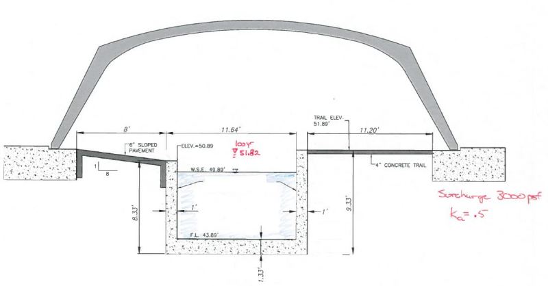
Capture_odmanr.jpg
 
Replies continue below

Recommended for you

you said your worst case is rapid draw down, but are you sure you will ever have fully saturated soil on the back side? is there a high water table? if the channel is connecting two basins, than have you looked at the outflow hydrograph? how long and how deep does the channel flow? Also consider how much leakage through joints that you will have during that time. assuming you use waterstops, it doesnt seem likely that you will ever have a fully saturated condition (unless you purposely make holes in the wall for weeps). suggest that if you want the drains, than use flapgates to keep water from entering. I would keep them at least a foot off the bottom.
 
It's a little difficult for me to see the dimensions. I assume this section will be for a contractor to use. However, if you're working in feet and (decimals) tenths, where does your contractor get small measuring tapes, other than with a surveyor, that has feet and decimals?

If yoou use drains, then you need to get involved with suitable filters at the inside openings, meaning extra cost.
 
Thank you all for the input.

Oldestguy - The land department drew this up as a preliminary drawing so zero engineering has been done yet. Their CAD designers work in decimal feet for the most part. We will convert everything other than stationing to feet and inches when we do the structural design.

PEinc - I will check for buoyancy. We might have to thicken the walls or base, or add little heels to the wall to pick up some of the earth load in order to hold the channel down. Also, the surcharge load is so large that the walls might have to get thicker just to handle the moment.

The top of wall is at elevation 51.89 and the 100yr elevation is 51.82 which is essentially the same. I have to assume in a 100yr rain significant water could be behind the walls, thus I am assuming we will design for full hydrostatic and earth pressure behind the walls.

Do you think we should put drains in though? If I design for the full hydrostatic pressure then do I care if it drains? It's Texas so after the backfill we will have expansive clay behind the walls that is not that permeable.

The flap gates suggested by CVG seem worth investigating. But if they are below water with ~9 ft of head pressure above them, then how would slow seepage ever open them?
 
Why would you take decimal feet and convert to feet and inches??? That seemed so archaic. I hated when our field guys measured things in feet and inches (say, depths in pile driving) - makes subtracting and adding a whole lot more cumbersome. (hint - go SI)
 
Would the depth of groundwater table play a big part. Say groundwater was 50m deep. If you had the channel running half full all the time wouldn't water weep out to the backfill and drain away and you would be loosing water? Probably very slowly but would depend how much filter material you have as this would fill up until it hits your clay.

I would consider trying to make the channel watertight i.e. no weep holes. My last place never liked using weep holes as they are prone to blockages. We would run a perforated nova coil pipe wrapped in a filter sock parallel at the base of the wall. This would be back filled in 300mm width of filter material extending the full height of the wall. Discharge it to the downstream pond. I suppose CVG may argue the point of non return valve Weep holes.

Then you could design it with no hydrostatic pressures and be more confident that there would be none give a perforated pipe full length of wall is much less prone to blockages.

If you design the wall for empty channel and full hydrostatic that is the worst case scenario. Designing with full hydrostatic pressure may beef up your wall by what.... 30-40% (just a guess).


they would only need to open when the water in the channel recedes
 
Hey BigH: I'll make a bet. If you go to 10 different lumber or hardware stores in Texas and try to find a tape measure that you use every day on the job as a carpenter, there won't be one that has that tape that is in feet and decimals. Part of the mind set that now has USA marking speed limits only in miles per hour, not metric any more because that trial failed some years back.
 
Based on my interpretation, the channel has more in common with a cofferdam than retaining walls. Agree with ErieChCh, omit drains and design the channel as watertight.

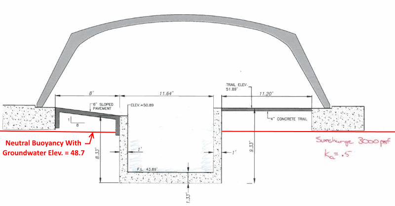
Also, suggest taking PEinc's comment seriously. My calcs indicate that neutral buoyancy for an empty channel occurs with water table at Elevation 48.7. For water table higher than 48.7 it definitely does float... might not pop up right away, but sooner or later it can happen.

Drainagechannel_pcmyqm.png


[idea]
[r2d2]
 
I have a decimal tape measure, got it at home depot. In general, civil plans are always in decimals. Forms are built off the structural plans which are in inches. I still take issue with the channel being 10.64 feet wide which is 10' 7-11/16" (approximate)
 
cvg: This issue has been around a long time, draftsmen and carpenters using different systems. Back in 1947 after my fist year in college my summer job was drawing up plans for the layout of equipment in a furniture factory. Having had my first year freshman surveying out of the way, I figured the drawings should be in feet and decimals. So I used the company's tape measure to get data for the drawings. Part way through the field steps I come across a dimension of X'-11-1/2 " on the tape. You can bet that was quite a shock. A lot of fixing had to be done where the drafting machine had only feet and decimals. I found good use for an erasing shield.
 
I don't think there's any good reason for wall drains if you are designing for at rest earth pressures and hydrostatic pressure. If anything during times of flood, you'd increase saturation - i.e., under what conditions would the hydrostatic pressure in the retained fill actually develop water-table conditions?

I think the nature of the foundation loads can be addressed using elastic theory.

I hate inches too!

f-d

ípapß gordo ainÆt no madre flaca!
 
Being that the site is in an area with expansive clays, maybe some extra precautions are needed. Will there be excessive loads on the side walls and could a long dry period then result in uplift when rain returns? This probably calls for some hinge joints of the whole thing spaced along its length as well as more reinforcing in the walls for excessive side loads. That paving and the canopy (why needed anyhow?) may have to be built to allow for foundation movements.
 
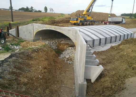
The canopy is not a canopy. It is a pre-cast & pre-fab c-span bridge on a shallow spread footing. I'm waiting on the exact loading that the bridge footings will be sending to the soil, but I have the soil report and I know the allowable bearing capacity is 3000psf, so the bridge must be shedding less than that. It will be a significant surcharge sent into the soil. 3000psf*50% / ~125pcf soil = ~12 additional feet of soil load applied to the side walls, which means they are effectively 20ft tall walls. The current 12inch wall thickness might not work.

For State and/or municipal jobs, this bridge would be sitting on drilled shafts or piles, but this is a private job. Oftentimes, the private developers prefer spread footings for cost savings. They are not as concerned about long term scour or maintenance. Also, these are "constant level" man-made detention ponds that are being spanned. They increase in depth for a time period after a rain event and then drop back down.

I believe that when this job started, the size of the detention ponds was smaller. They have since been increased and the hydrologists needed more channel cross section area to move water across, which is how we got to the current channel configuration.

All I know is that I have the current cross section to work with. We had the geotechs modify their original report for the new proposed cross section and perform a global stability analysis. They have signed off and sealed their report addendum.


Joe: Nice to hear more. A common problem with posts first placed here is giving only part of the info. Considering the expansive soil, that "standard" foundation, such as piles, may well be needed. I suspect the design of the "bridge" calls fr some lateral resistance of the foundations due to the inclined "legs" of the bridge. It sure seems like an arch, requiring that lateral resistance at the foundations. Under those circumstances the bridge and its load may not have much of any effect on the channel.
 
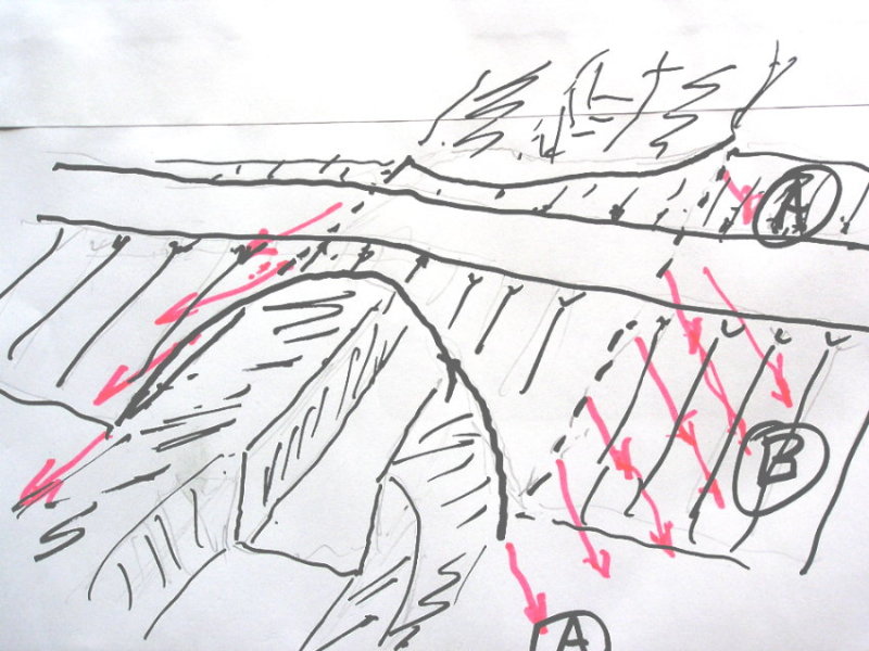
Am I assuming right that there will be no side walls or retaining walls to hold the roadway, but instead sloped sides of the embankment? If so the different loads per lineal foot along "bridge" feet (A versus B) in expansive soils may well result in more expansion at A as compared to B where loads are heavier.

P1010473_aydjwf.jpg
 
Maybe this one? Again considerable difference it loadings from the bridge main fill versus slopes

bridge_with_wing_walls_ljrpmo.jpg
 
Status
Not open for further replies.

Part and Inventory Search

Sponsor