Continue to Site

Eng-Tips is the largest engineering community on the Internet

Intelligent Work Forums for Engineering Professionals

  • Congratulations KootK on being selected by the Eng-Tips community for having the most helpful posts in the forums last week. Way to Go!

Drill the I beam in the center of the flange

TClick

Mechanical
Dec 2, 2024
3
Hi all,

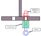
I've been asked to assess whether it's acceptable to load I beam with several concentrated loads. The load is not high so in general, this seems fine. My concern is that the connection of the load is through eye bolts will be installed on the treaded hole tapping in the central of the flange to part of the web However, my concern lies with the method of attaching these loads. The loads will be connected through eye bolts installed in threaded holes located at the center of the flange, extending into the web. I’ve never encountered this type of connection before and am unsure if it’s acceptable. I was initially thinking about applying a reduction factor for the flange and web area based on the hole-cutting area, but I am not sure if there is safe enough. Is there anything I have missed?
Has anyone encountered a similar situation or found any code references that address limitations for such connections?
1733179737137.png
I considered offsetting the holes from the center line to create a zigzag pattern, but this would introduce a torsion to the beam in the segments. Between these two options, which one do you think is better? Thanks in advance.
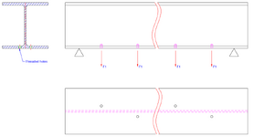
1733179764499.png
 
Replies continue below

Recommended for you

I would take the offset version, complete with the nominal torsion, all day long.

That said, I don't know that the tapped hole in the center is a structural problem of any sort. Like many other things in steel detailing, it's just a local disturbance in a thing generally thought capable of redistribution. It just seems weird, difficult, and maybe a little messy.
 
What diameter of eye bolt and what flange thickness? How deep do you need full threads for the eye bolts? You did not ask for other suggestions, but, can you weld threaded blocks to the beam? Eye brackets and clevis? Seems like there are multiple options to hang loads. Is this a structural load or a mechanical load?
 
What diameter of eye bolt and what flange thickness? How deep do you need full threads for the eye bolts? You did not ask for other suggestions, but, can you weld threaded blocks to the beam? Eye brackets and clevis? Seems like there are multiple options to hang loads. Is this a structural load or a mechanical load?
Hello dvd, thank you for your advice. The eye bolt is M12, and the flange thickness is 14.2mm. This is for a temporary jig to hang the components for painting, and I assume that the load is primarily the dead load. I have proposed the welding, clamping, or wrapping chains but I think the team prefers to proceed with the threading method due to other factors.
 
I’ve seen the centre version. It’s not something I’d detail without a reason, but if someone else wanted to do it, eg that’s how they bolt their rail to a beam, I wouldn’t have a problem.
 
threaded holes into the web looks like a nightmare to fabricate and not a good joint concept.

thru holes thru the flanges with nuts on the back side is a better joint design.
 
Hi all,

I've been asked to assess whether it's acceptable to load I beam with several concentrated loads. The load is not high so in general, this seems fine. My concern is that the connection of the load is through eye bolts will be installed on the treaded hole tapping in the central of the flange to part of the web However, my concern lies with the method of attaching these loads. The loads will be connected through eye bolts installed in threaded holes located at the center of the flange, extending into the web. I’ve never encountered this type of connection before and am unsure if it’s acceptable. I was initially thinking about applying a reduction factor for the flange and web area based on the hole-cutting area, but I am not sure if there is safe enough. Is there anything I have missed?
Has anyone encountered a similar situation or found any code references that address limitations for such connections?
View attachment 1831
I considered offsetting the holes from the center line to create a zigzag pattern, but this would introduce a torsion to the beam in the segments. Between these two options, which one do you think is better? Thanks in advance.
View attachment 1832
If the loads are small the nominal torsion usually will be fine, plus since you have loading on both sides of the web it will tend to balance itself out.
 
Instead of drilling and tapping threads in the bottom flange, how about welding a single row of threaded Nelson studs to the bottom flange and then connecting the eye bolts to the threaded studs with a threaded coupler? The only problem might be matching the threads of the Nelson stud with the threads on the eye bolt.1733201923216.png
 
Do you imagine this happening in a shop, or in the field, working overhead?

Regardless, drilling an taping "perfect" holes as you've sketched them will be nearly impossible.

Why not through holes with a nut on the top?

If you want the load on the centerline, then why not through holes, U bolts and nuts on the top?

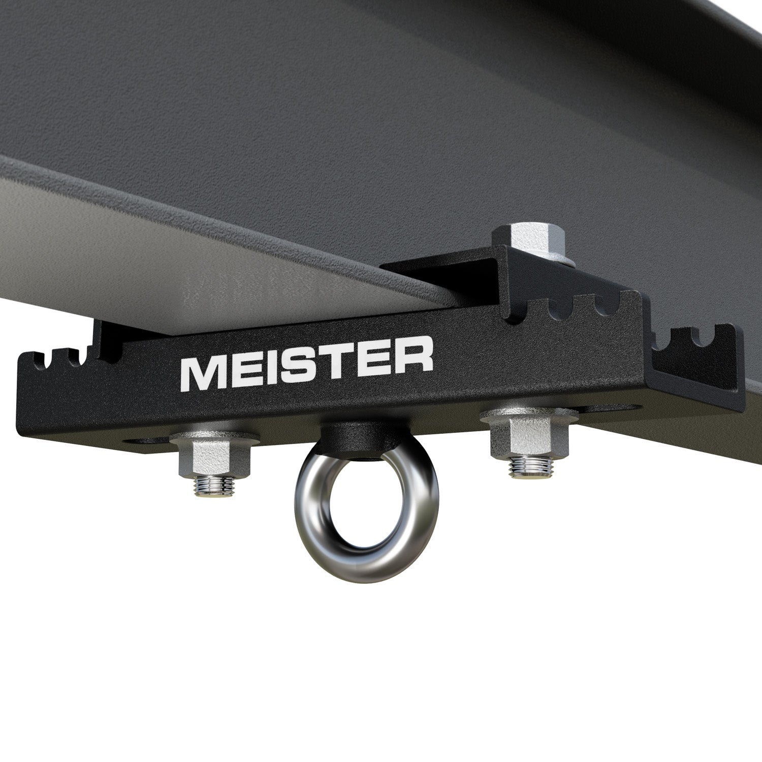
There's a whole universe of clamp on hangers. None of them work for you?

As examples:
 
Hmm lots of opinions! Like others I'd mostly be happy enough will drill and tapping if it calcs out suitably. I'd prefer it over a eccentric drill and tap into the flange.

Though there are half a dozen other choices that I'd choose before drilling and tapping.

In fact I don't see many good engineering reasons for drilling and tapping here. Architectural reasons, maybe.
 
I think if you're going that way then limit the depth of the tap to the thickness of the flange. That might reduce the load capacity of the eye bolt but anything more and the hole and thread risks breakthrough and lack of strength.

Plenty other options. Weld on a small plate to increase thread length?
 
I haven’t seen anyone propose this approach:

X-BT from Hilti can do what you need. A small pilot hole (not a through hole) is drilled partway into the flange. The fastener is driven into this pilot hole; it effectively welds itself into the base metal. Part of the fastener that extends above (below, in your case) the base metal is threaded.

X-BT sees great use on offshore oil rigs and in certain other industrial applications. I don’t see them much in buildings.
 
Do you imagine this happening in a shop, or in the field, working overhead?

Regardless, drilling an taping "perfect" holes as you've sketched them will be nearly impossible.

Why not through holes with a nut on the top?

If you want the load on the centerline, then why not through holes, U bolts and nuts on the top?

There's a whole universe of clamp on hangers. None of them work for you?

As examples:
Hi Mint, think you for all advice and suggestions. I particularly like the U bolt idea. The I beam is intended for a temporary jig in the factory to hang the components for painting. The factory prefer to involve only drilling and tapping for this job due to the equipment and space limitations. Welding might take more material and time. We already have eyebolts in stock so instead of purchasing new beam clamps, we would like to use the existing stock items first.

I think a through hole with nut will be a better solution as well, but he thread length of the stocked eyebolt is 18mm, which leaves insufficient space to secure a nut on top. Thanks again for your input.
 

Part and Inventory Search

Sponsor