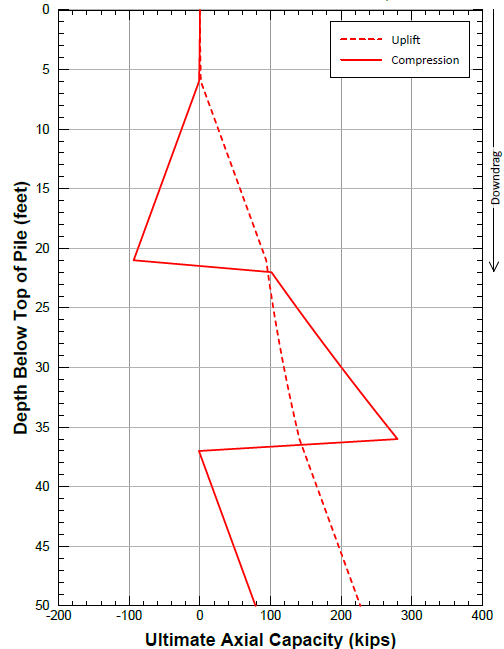
Below is a static axial capacity plot for a driven pile that I just received from a nationally recognized geotechnical firm (to remain anonymous).
Soil profile is layered silty-sand then clay then silty-sand ... (near a river).
In my humble opinion, this plot is garbage and makes no sense. I am going to recommend to our project manager to fire the GE and write a new contract for another GE.
[My bias: My pile influences are primarily Fellenius and FHWA (which explains Fellenius a little bit better than Fellenius).]
Here's my questions for the seasoned geo engineers:
1) Is there any defense of the plot as shown? It appears that the GE is reducing (even going negative) the ultimate axial pile capacty due to drag forces (which he incorrectly terms downdrag).
For ultimate capacity, aren't all the soil friction vectors pointing upward?
2) Seems like a plot showing the neutral plane with a fixed pile length would be more helpful, but this is uncommon. Does anyone provide load transfer plots in their geo reports?

