Continue to Site

Eng-Tips is the largest engineering community on the Internet

Intelligent Work Forums for Engineering Professionals

  • Congratulations IDS on being selected by the Eng-Tips community for having the most helpful posts in the forums last week. Way to Go!

Dual Voltage, Single Phase Motor Wiring Question

Status
Not open for further replies.

shandleyman

Electrical
Apr 3, 2017
6
Hello,

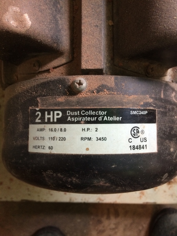
I have a friend who has an older PowerSonic dust collector that is a dual voltage (listed on the nameplate as 110/220VAC). It is currently hooked up to run on 110VAC.
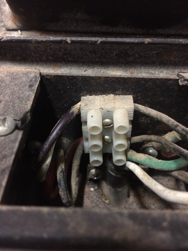
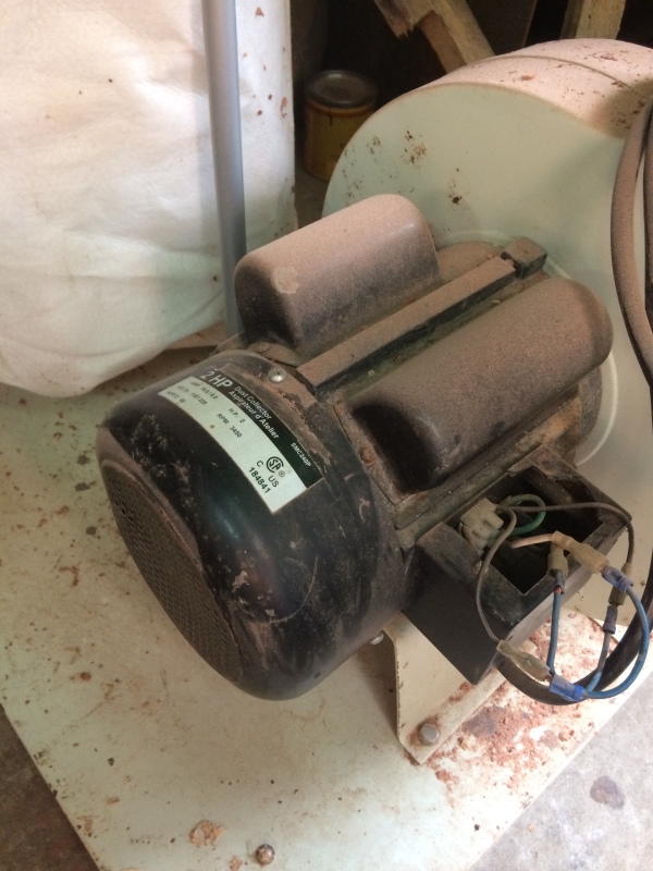
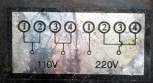
There is NO paperwork at all but a nonsense wire diagram behind the cover that shows wire or terminal numbers but the wires/terminals are NOT numbered (see pics).

The motor has some info on it but aside from the voltage, frequency, rpm, and amperage, etc, it has the part number SMC240P. That's it.

Currently, the wires are hooked up as such (for 110VAC operation):

Black (hot) from Power Cable goes to a faded black (could be purple) and white wire.
White (neutral) from Power Cable goes to a Red and a Black wire.
There are a couple splices of different colored wire in the pics below but this is the way it is hooked up.

I am wondering if any of you can help out with this dust collector to change it to 220V. I also challenge your googling abilities to find a proper schematic for it.

I am trying to get the owner to take some readings with an ohm meter between the 4 wires. I will provide that information when it is available.

Please ask any questions and I will be happy to help.

Thanks in advance!
17758031_10154859945337400_176942187_n_sfjp4b.jpg
IMG_5177_hdvtim.jpg
IMG_5178_iqbjca.jpg
IMG_5179_q5fuqy.jpg
 
Replies continue below

Recommended for you

Pick one side as the #1 and wire it up as diagrammed for 220. Try it. If it's wrong you'll know instantly and can shut it back off. These things have some serious thermal mass and will not be damaged in one second. If it doesn't work re-wire it with the other end as #1.

Keith Cress
kcress -
 
Thank you for the response.

The way I see it, there are 4 different combos I can try to match the wiring diagram for 220VAC:
1------L1
2&4------Jumped Together
3------L2

A: Purple-1(L1), White&Black-2&4 jumped together, Red-3(L2)
B: Purple-1(L1), White&Red-2&4 jumped together, Black-3(L2)
C: White-1(L1), Purple&Black-2&4 jumped together, Red-3(L2)
D: White-1(L1), Purple&Red-2&4 jumped together, Black-3(L2)

How would I go about making an educated decision choosing one that would work?

Thanks again!
 
Label the both the wires connected to the white wire as + or N or something else.
Label the both the wires connected to the white wire as - or H or something else.
Identify each winding. Each winding should have + on one lead and _ on the other lead.
Connect them in series with
L1 to H,
N to H
N to L2.
N -------H_N-------H

Bill
--------------------
"Why not the best?"
Jimmy Carter
 
I'm sorry, I've tried to figure out what you are saying there and I am not quite getting it.

Right now, for the 110VAC it is hooked up like this:

Purple&White - 1&2 Jumped together > Hot BLACK Wire
Red&Black - 3&4 Jumped together > Neutral WHITE Wire

So you are saying to label the Purple wire as N, the Red Wire as N
Then the Red wire as H, the black wire as H.

From there I am confused. How do I identify the windings's leads?

 
I'm sorry.. Looking at your first picture I didn't notice it only has 3 terminals not the 4 needed.

Currently you have the HOT wire that's black connected to two wires.
Label those two wires (+).


You have the Neutral wire that's white connected to two wires.
Label those two wires (-).

Now with the power completely OFF.

Disconnect all the wires so you have four flying leads sticking out of the motor.
Ignore the power leads coming to the motor, likely a black, white, and safety ground green.

Using an ohm meter find which of the leads have continuity between them. It should be one each of the (+) and (-) leads. Mark the pairs by adding and (A) to both of the pair that have continuity.

You can label the other two that should have continuity (B).

Now you hook up the power L1 to (A+) and L2 to (B -) and then hook (A-) to (B+).

L1--(A+)
(A-)--(B+)
L2--(B -)


Keith Cress
kcress -
 
Hi Keith. The start winding must be internally connected across just one of the run windings.
I'm hoping that the run capacitor is a double capacitor with one section connected across each run winding.
I have another suggestion for labelling.
Number the wire connected to line one as #1 and #2.
The wire with continuity to #1 will be #4 and
The wire with continuity to #2 will be #3.
Then use the connection diagram.

Bill
--------------------
"Why not the best?"
Jimmy Carter
 
Ok, labeled the purple wire #1 and the white wire #2.
So the purple has continuity with the black so the black is #4
The White wire (#2) has continuity with the red so it is #3

Purple #1
White #2
Red #3
Black #4

Purple - L1 (240VAC)
White & Black - Connected together
Red - L2 (240VAC)

Testing soon!


Be aware; Free advice on the internet is worth what you pay for it. Grin
Seriously, there are two capacitors shown,normally these would be a starting capacitor and a running capacitor.
Also there is a starting switch on a motor of this size.
Permanent split capacitor motors are generally smaller.
We have to hope that the internal connections to these components are correct for both 120 Volt operation and for 240 Volt operation.
Those connections are generally accessible.
The connection diagram shown seems to imply that there are internal connections to the other components.
As long as no-one has been inside and changed the connections you should be OK but we have no way of knowing from a distance if the internal connections are correct.

Bill
--------------------
"Why not the best?"
Jimmy Carter
 
well, sure enough, the motor started up but did not get to full speed before the small capacitor got hot and a let some of its smoke out. :(
the advice i got from these posts, well, they were confirming what is in my motor books. without taking the whole thing apart, who knows what has happened in terms of wiring in it's life.
 
The starting switch may have failed and kept the starting winding and the start capacitor in the circuit. If that happens, the winding and the capacitor may have a race to the designated smoking area to see who gets to smoke first.
The other capacitor may be a dual capacitor. One section of the capacitor should be connected across each run winding.
If some time in the past, both sections of the capacitor were connected across one run winding the motor would run on 120 volts but the capacitor would probably smoke on the 240 Volt connection.
I would check the starting switch first.

Bill
--------------------
"Why not the best?"
Jimmy Carter
 
I was thinking the same thing but... when you say starting switch, you are talking about the centrifugal switch that drops the cap and start winding out, correct?
 
Status
Not open for further replies.

Part and Inventory Search

Sponsor