Eng-Tips is the largest engineering community on the Internet

Intelligent Work Forums for Engineering Professionals

Dynamic and Static Thrust Forces - What is considered "Problematic"

Status
Not open for further replies.

NW_Wash_Eng

Mechanical
May 22, 2024
14
0
0
US
thread164-494356
Good morning all,

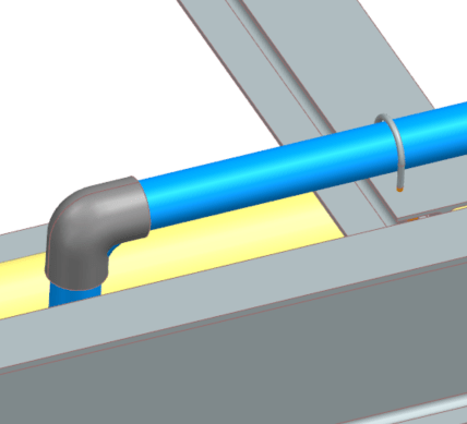
I have been tasked with figuring out where to install thrust bracing on 90deg elbows for an open pipe system. These are going to be a mix of SCH10 SS and SCH80 PVC pipes, varying anywhere from 1" to 12" in diameter. My thought process here, and please correct me if I am wrong, is to calculate the static pressure force and sum it with the dynamic force that the fluid flow will be causing. I believe an example might be the most efficient way for me to go through this;

System knowns:
Pipe size: 12" SCH10 304SS
Fluid Flowrate: 2600GPM
Gauge Pressure: 10PSI
Assume fluid is water or comparable

Using the info above, I get a cross sectional area of roughly .837ft^2 at a velocity of 6.919ft/sec
Static Pressure Force=gauge pressure*144*cross section of pipe
= 10psi*144*.837ft^2
=1206lbf
With the *144 being a unit conversion​

For Dynamic force, I referenced this:
more specifically, this: R=ρAv^2(1-cosβ)
Dynamic Force=R
=(density of water/gravity)*cross section of pipe*velocity^2*(1-cos(angle of elbow))
=(62.4/32.2)*.837*6.919^2*(1-COS(90))
=112.47lbf
For my own notes, dividing by gravity to get units into lbf from lbm​

Summing these two, I get 1318lbf.

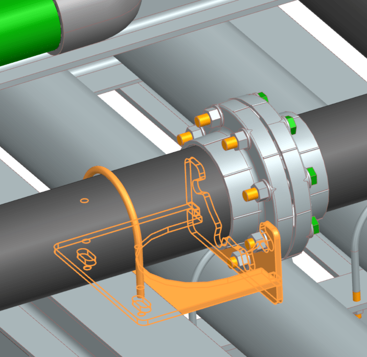
My main question here is, what do I compare this to in order to understand what is "too much" or going to become a problem over time? We plan to secure the pipes to our racks with standard u bolts. To prevent crevice corrosion on the SS pipes, we are adding strips of UHMW between the pipes and the racks. I am worried we will not be able to tighten the u bolts enough to hold the pipes down fully on that UHMW. I am also worried we would crack the PVC before we got to a point where we could react these summed forces correctly.

Is there a rule of thumb that is something like "1500lbf or greater on pipes sized X through Y needs thrust blocking?"
 
Replies continue below

Recommended for you

What's your jointing?

Weld? Push fit?

U bolts should never be used as clamps or anchors

What do you want to restrain the pipes?

Thrust blocks are for buried push fit pipes not ones on a rack.

Remember - More details = better answers
Also: If you get a response it's polite to respond to it.
 
Hello again LittleInch!

"Thrust Block" is not the correct term here. We are calling a weldment that we mount to the exterior of the pipe flange to react the thrust force as a "thrust block". I am not sure who came up with the name for the weldment, honestly. Here is a photo of one for reference:
Screenshot_2024-07-18_142834_yjj4ay.png


Jointing for the SS is all welded. BW fittings, except the flanges where we tend to use slip ons. PVC pipe is mostly socket connect.

Your comment on pipe restraint has be concerned. My understanding is that u bolts are a fairly common pipe anchoring method. Is this not the case? I have attached a photo of a small PVC pipe with a u bolt drilled through the rack to secure the pipe.
Screenshot_2024-07-18_142457_yslz8q.png
This is fairly typical for what I am seeing in my 3D model.
 
Welded pipe or pvc glued joints do not come apart with thrust loads due to internal pressure or elbow momentum forces so you do not need thrust anchors. They are only required where the piping joints will come apart with thrust loads (like underground cast iron bell and spigot pipe). Your reasoning is correct though that the sum of forces would be the pressure thrust load plus the momentum thrust load at elbows as you indicate in your post. However for connections that can transfer load without coming apart, this force is transmitted axially through the joint and piping and equalized by the same elbow force at the opposite side of the run of pipe.

The u-bolt you show only restricts pipe from moving laterally. It also restricts small piping from moving axially but large pipe will slip with u-bolt if load is heavy enough. Sometimes if you want to stop some axialy force with u-bold sometimes a lug is welded to the pipe at the u-bolt but this is not done when significant forces are involved. Proper anchors or axial would need to be designed for significant forces.

I don't think the u-bold weldment thing you show performs any function whatsoever because it is attached to the pipe itself so it moves with the pipe. If au-bolt is to provide restriction to movement it must be attached to the structure that the pipe is supported on.

Furthermore for pipe with joints that cannot take any load before separating then any load is problematic so you would always need external restriction at elbows and other changes in direction.
 
U bolts should in only be used to guide and stop pipes moving laterally or vertically. They should be industrial with amin 5mm clearance around the pipe

Far too often people try to use them as anchors or full restraints at which they are terrible. Their point loud and stress concentration is awful and many pipe failures are due to incorrect use of U bolts as anchors.

Remember - More details = better answers
Also: If you get a response it's polite to respond to it.
 
Thank you all for the comments, this is great!

Perhaps the image above is not the best to properly portray the use of the u bolts, here is an overall of a single route. Y axis is roughly 160' and X is roughly 53' with the green being the pipe.
Screenshot_2024-07-22_065024_uxikir.png

Our thermal expansion should be minimal as we are in a heated building and fluid temps are not to exceed 100F. My understanding of the placement on this pipe (very official red lines drawn with MC paint represent U bolt locations) is that we are hoping the thermal expansion we will see should be absorbed by the direction changes. Now that I say that though, if we anchor the pipes with u bolts there wont be much space to grow or shrink..
We do use the weld on lug style to stop movement on our SS pipe. We don't seem to have a comparable solution for PVC yet. Any suggestions?
So this brings up my next question, what would the proper anchoring be for this PVC pipe? I definitely agree with LittleInch about the point loads and stress concentrations seen around the u bolts being tightened around the pipe. Seems problematic to me.
The weldment I showed in my previous post is actually secured to the rack using the u bolt. We drill holes into the rack for the u bolt to go through and then bolt it to the flange. The picture is a little hard to follow so my appologies for that. The top of the plate actually mounts on the underside of the beam flange.
I also apologize for all my rookie questions here. I have inherited this project from 2 previous owners and trying to interpret their intentions and also learn the proper methods has been challenging to say the least.
 
Good god, who located those "anchors there?

Going from the left, the first one maybe, no 2 should be at the midpoint, nos 3 and 4 need to go and no 5 prob moved back towards the tee. but do a stress analysis on it. PVC is a brittle material and can snap before you can see it is over stressed. The vendors often have good manuals or ways to do things that we wouldn't have thought of. They may even supply inline bits which allow you to anchor the pipe.

U bolts are designed to hold pipe stanchions to steelwork or fix things like instruments to a circular pole. They should never be used to clamp pipe which has an axial thrust to try to stop it moving. Just results in failure.

You can fit a pair of flanges and then clamp the flanges using the bolts or fit a thicker section and then clamp two half shells around it with some slightly squashy material between the clamp and the pipe.

U bolts could be used as guides and vertical restraints, but the the risk is someone goes and clamps it down as they don't understand why you wouldn't, so better not to use them at all IMHO.

On your flange clamp thing just throw the U bolt away - does nothing for you and again someone will screw it down.

Remember - More details = better answers
Also: If you get a response it's polite to respond to it.
 
Someone who didnt know what they are doing, and I'd like to not make the same mistake, lol!
My gut tells me to do this:
Screenshot_2024-07-22_065024_uw2oos.png

Anchor at the ends and one in the middle. This would allow freedom to move in the direction if the green arrows. Please note, no Z movement . Placing the anchor in the middle of the long y run would essentially turn the two halves into a couple expansions legs. I am expecting 1.46" of expansion in both the pos and neg Y in the longest Y axis leg with the anchor. If I anchor it in the middle, I can control the expansion to go to the corners. Does this logic pass your gut test? I will look into running some pipe stress calcs here shortly.
Also, I totally agree about losing the u bolt on the flange clamp. Not sure why those were originally proposed.
 
As a first pass looks ok to me to go and see what the stresses / movement are in your elbows.

That short leg on the left is a bit "stiff" looking though. You might need to move the line stop / anchor closer to the left to reduce the amount of movement coming into the short leg of the Z. Ideally it should be located where the stress program shows zero movement if you analyse it without an line stop, only a guide.

Others may have a different opinion. An experienced pipe stress person will sort this in a few hours.

Also watch out for how you allow the pipe to move. Rubbing bars don't work well on PVC - you really need shoes to prevent a hole being worn into the PVC or prevent a lock up IMHO.

Remember - More details = better answers
Also: If you get a response it's polite to respond to it.
 
Again, great input. Thank you much!
Out of curiosity, what pipe stress program are you using/ would recommend? I am not sure I have one at my disposal but can recommend my company look into one. I believe I have an argument to get one without much fuss.
I am proposing we bolt strips of "slippery UHMW" to the top of the resting surfaces to prevent crevice corrosion between our galvanized rack and SS pipes. I can just extend it further to run under the PVC too. I believe it is softer than the SCH80 PVC, so should wear before the pipe does while giving me the movement I want.
 
I'll let others answer that.

Caeasr II is popular but there are many others and some may have better ways of looking at PVC. Ask the pipe vendor what they would use or recommend.

Remember - More details = better answers
Also: If you get a response it's polite to respond to it.
 
Is the green line in your screenshot the 12" SS piping? If so then I get a thermal expansion of the longest "Y" run which appears to be 120 ft long at 0.6 inches maximum. This assumes installation temperature of about 60 F and 40 F for differential temperature for thermal expansion, with alpha SS = 11x10[sup]-6[/sup] which is conservative. For this line I would put a limt stop or anchor in the middle of the line run where you show it moved to now. This would minimize the loading on this anchor. Most of the loading on the anchor is when the pipe starts thermally expanding and then the force on the anchor will be the friction force due to the normal weight of load on the pipe support times the coefficient of friction on the support. The dirction of the friction load would be opposite to the motion and towards the anchor. By locating the anchor in the middle then equal friction loads with exist on each side of the anchor pushing on it and balancing out for minimum net load on anchor. An anchor in the middle will allow thermal expansion of the long lenghts into the elbows/change in direction at the ends. So putting the anchor in the middle of the run you would get 0.3 inches expanding into the connecting runs at the ends. I would also install guides about every 20 feet on the long run to prevent sideways movements and take any sideway loads such as earthquake. I would not put any guides or restrictions with 10 feet or so of the elbows as to not restrict thermal expansion from perpendicular pipe legs. The actual minimum distance of elbow to guide can be checked with stress analysis or with estimated pipe stress methods such as the guided cantilever beam method.

It looks like the short "X" run at the left end where the pipe turns is about 10 ft long with negligible thermal expansion of about 0.05". This 10 ft offset should well enough to take 0.3 inches of thermal expansion. I would put a guide in the middle of this run with a 3/8" gap. This will allow the long pipe run to expand into it but keep some restriction on lateral movement.

The next "Y" run going towards the tank appears to be about 20 ft long with negligible expansion of 0.1" approx. I would put a axial line stop or anchor in the middle of this line with guides also placed but again not too close to elbows. This will provide both lateral and axial movement limitation at this point. With this section fixed and the other long "Y" run fixed with anchors/stops in the middle an with guides also included, the entire piping system will be fixed in both "X" and "Y" directions.

I would not put any vertical restriction on the short "X" run before the vertical up to the tank nozzle. If tank themally grows vertically due to temperature any vertical restriction on that short run will overstress the pipe. I would just put a bottom support with guide and 1/4" gap on guide. You may need to check the load on your tank nozzle with this arrangement considering that if the pipe starts lifting off the support on that short run, it will put the weight of the vertical pipe run to the top of the tank all on the tank nozzles. There may need to be a support on the vertical run of pipe to keep load off the nozzles and/or nozzle may have to have stout reinforcement pad installed.

Looking at the other end of the system the perpendicular run to the long rung to the right which appears to be about 40 ft. long, I would put an anchor/stop in the middle with guides also installed on this segment to within about 10 ft more or less of the elbows with 3/8" gap. This will allow for thermal expansion of the long run, allow for themal expansion axially of this short run, and provide restriction in both the "x" and "y" directions.

For the last "Y" run to the right which appears to be about 20 ft or so long again I would put an anchor or axial stop with guides in the middle of the run and install guides on other support to within about 5 feet or so from the elbows since not much thermal expansion is going into this pipe.

I would then check with a piping stress analysis program and adjust as necessary. I use Caesar II mostly but have used autopipe. Autopipe is mostly what is use in waste water treatment systms for some reason.

Also note that for Sch 10 SS the pipe wall is very thin so if spacing between supports gets too long such as around 20 ft or longer, the local load of the pipe weight on the pipe support may overstress the pipe wall locally. In this case wear pads are put on bottom of SS at supports or pipe spans are kept to a minimum.
 
I think it was a PVC pipe.

That expands a lot more than Stl Stl.

Remember - More details = better answers
Also: If you get a response it's polite to respond to it.
 
This specific run is PVC but this is great information for me to reference! Thank you for taking the time to provide your input! Due to the design of the rack, our pipes will be resting on UHMW roughly every 4' or so, so we should be good on local loads.
I do believe this gives me enough information to be dangerous as of right now. If anything else comes up, I will be sure to reach out. Thank you everyone for your input!
 
Status
Not open for further replies.
Back
Top