The grounding scope is to reduce the current through the grounding grid in order to improve touch and step potentials.
Only 10 kV short-circuit current could participate in potential rising.
So single phase to ground short-circuit could be 10-30 A
The phase-to-ground-to-phase could be high-usually 0.75*I"k3.In your case a maximum 20 kA it could be.
If the substation circuit breaker trip delay is not more than 3 sec. 240 mm^2 copper temperature will be less than 250oC.
I cannot say if this cable will significantly reduce the current or not.
An example of calculation is as follows:
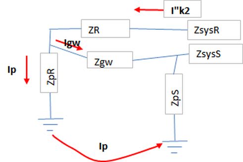
Where:
Zsys-supply system impedance.
ZR=cable phase R including phase-to grounding reactance.
Zgw=grounding wire impedance
ZpR =grounding resistance at R phase-to-ground fault
ZpS=grounding resistance at S phase-to-ground fault
If three phase short circuit current will be 30 kA the system impedance could be 10/sqrt(3)/30=0.2 ohm.
The grounding resistance could be 1 ohm.
Let's say the distance to substation will be 1 km.
Let's say the soil resistance 100 ohm.m then the grounding depth Dp=2.085/sqrt(f/ro/10^9)/10^3=93 m
XL=0.145*LOG10(Dp/rc)=0.145*log(93000/0.779/10)=0.59 ohm
The cable 240 mm^2 copper resistance will be 0.1 ohm.
A simple calculation the current through ground according to the following sketch:
If no grounding wire exists Ip=I"k2
ZR and Zgw include wire-to-ground reactance.ZS=0 –the S fault is located at the source.
Let's say the supply cable 15 kV 3 copper conductors 240 mm^2 XLPE insulated
ZR=0.1+j0.085 and parallel 2 phases-to-ground reactance 0.5 ohm
The I”k2 in the first case when no grounding wire is present =9200 A and this is the current through grounding
grid.
In second case in presence of grounding wire I”k2=9200 A but Ip=4420 A.