Continue to Site

Eng-Tips is the largest engineering community on the Internet

Intelligent Work Forums for Engineering Professionals

  • Congratulations KootK on being selected by the Eng-Tips community for having the most helpful posts in the forums last week. Way to Go!

Easy and Conservative Method to Calculate Fillet Welds? 11

Status
Not open for further replies.

Logan82

Structural
May 5, 2021
212
Hi!

I am trying to find an easy and conservative method to calculate fillet welds while using the results of FEM software structural utilization of members. I was interested to know if this method could be acceptable, and if you have other ideas to facilitate weld calculation:

Plate:
Linear Resistance to Compression in a Plate: crpl = 0.9 * Fy * tpl (Unit of Force / Unit of Plate Length)

Linear Resistance to Shear in a Plate: vrpl = 0.9 * 0.6 * Fy * tpl  (Unit of Force / Unit of Plate Length)

Max Linear Resistance in a Plate :  rplmax  = 0.9 * Fy * tpl (Unit of Force / Unit of Plate Length)

Weld:
Linear Resistance to Shear in a Fillet Weld (Weld) : fw1 = (0.67 * 0.67 * Xu) * (dw / sqrt(2)) (Unit of Force / (Unit of Weld Length))

Linear Resistance to Shear in a Fillet Weld (Base Metal): fw2 = (0.67 * 0.67 * Fu) * (dw) (Unit of Force / (Unit of Weld Length))

For Fu = 450 MPa and Xu = 490 MPa:
Min Linear Resistance in a Weld: fwmin  = (0.67 * 0.67 * Fu) * (dw / sqrt(2)) (Unit of Force / (Unit of Weld Length))


Where:
dw  = Weld Leg Size
tpl = Plate Thickness
Fy = Yield Stress
Fu = Ultimate Tension Stress


If we want to find the fillet weld size required so that the weld is as strong as a given plate thickness, for Fy = 300 MPa and Xu = 490 MPa, would it be conservative to affirm that:

rplmax = fwmin

0.9 * Fy * tpl = (0.67 * 0.67 * Fu) * (dw / sqrt(2))

dw = sqrt(2) * (0.9 * Fy * tpl) / (0.67 * 0.67 * Fu)

dw = 2.835 * (Fy / Fu) * tpl

dw = 2.835 * (300 MPa / 450 MPa) * tpl

dw = = 1.89 * tpl


Say you have a plate of 6.35 mm of thickness, then it would require a weld size of this size to be as resistant as the plate:

dw = 1.89 * 6.35 mm =  12 mm


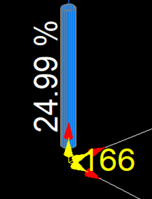
Now, if you use your FEM software that's used to calculate the structural utilization in a member, and find that a member near a connection is utilized at 24.99 %, the weld is all around a round HSS member (tpl = 6.35 mm), would you say it would be conservative to put a weld of this size:

dw = 2.835 * (Fy / Fu) * tpl * Utilization

dw = 2.835 * (300 MPa / 450 MPa) * 6.35 mm * 24.99 % = 2.99 mm
2021-09-08_16_22_12-Microsoft_Excel_-_200622-HQE-NDC-ACCES-AVAL-R11.xls_Mode_de_compatibilit%C3%A9_kln6j0.png


CSA S16 and CSA W59 were used in this calculation.
 
Replies continue below

Recommended for you

I didn't look at your post, but when I see easy and conservative way to calculate fillet welds, I think back to what I learned about my first day as an engineer.
Weld Allowable=.928 kips/(length in inches * leg in 16th)
So a two inch long 1/4 inch fillet weld has a capacity of 7.42 kips (4 * 2 * .928).
 
Sorry for the long post guys!

TLDR: the method I asked your opinion about finds the minimum weld leg size to equal the highest strength of a plate on which it is connected, and then reduce the weld size according to the structural member utilization to which it connects. I was trying to make profit of each load combination treated in my FEM software, instead of calculating the loads on my welds using the load envelope.
dw = 2.835 * (Fy / Fu) * tpl

JedClampett, thank you, I also use this allowable stress in weld calculations sometimes.

Thank you for sharing your calculation sheet dik!
 
Why, better to have more information than not enough... no need to be sorry, in particular, if you solved your problem.

Rather than think climate change and the corona virus as science, think of it as the wrath of God. Feel any better?

-Dik
 
TLDR: the method I asked your opinion about finds the minimum weld leg size to equal the highest strength of a plate on which it is connected, and then reduce the weld size according to the structural member utilization to which it connects.

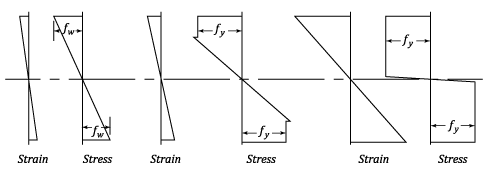
Just be cautious when using plastic section properties for member utilisation. Eg in I-beam bending, the last ~15% comes from the web. The flanges are at full utilisation from 85% of plastic section capacity.
 
Blodgett...Blodgett...Blodgett

 
Bl... Bl... Bl... Blodgett

I stutter...

Rather than think climate change and the corona virus as science, think of it as the wrath of God. Feel any better?

-Dik
 
Ron and dik, which Blodgett weld method are you refering to?

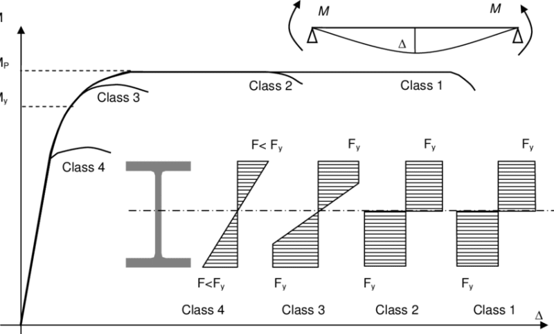
steveh49, good point. To illustrate your comment, let me take bring back Yao1989's comment from this thread
Yao1989 said:
My understanding is that class 1 & 2 are thick enough such that you can continue to allow high strain, and allow the extreme fiber to continue to deform past yield until the entire section above/below the neutral flange has yielded, thus all loaded to at least yield strength, hence you can use plastic modulus. You don't do this for class 3 & 4 because they are too thin and will buckle locally after the extreme fibers are past yield stress. In fact for even thinner sections you'll see on cold-form-steel, local buckling may govern the section before you even reach elastic yield of extreme fiber.
main-qimg-9737b759b7ad92bf28091fe4a1344022_mjcjuj_methbh.png
Source:
If my understanding is correct, since welds can't sustain high strain, the stress will be higher at the flange than in the web of an I beam. So the method I have shown can't work with class 1, 2 and 3 sections, but can work with sections of class 4:
Effect-of-local-buckling-on-the-moment-capacity-of-I-section-beam-classification-of_lbpwyo.png

Source:
 
The strain in flanges vs web is a good discussion, but not sure where the idea of "...since welds can't sustain high strain..." came from.
Unless you have a highly restrained joint (i.e. triaxial restraint), the welds can indeed sustain high strain - at least for mild steel and HSLA used in structural steel along with just about any decent toughness filler metal.
 
Logan82 said:
Linear Resistance to Shear in a Fillet Weld (Base Metal): fw2 = (0.67 * 0.67 * Fu) * (dw / sqrt(2)) (Unit of Force / (Unit of Weld Length))

For the base metal check, its capacity should be based on the thickness of the base metal and not the size of the weld.

The only way your method would work would be if the member capacities used for your utilization value were just a check that the stress does not reach the yield stress. Your capacities, though, are likely based on the plastic capacity where the edge of the flange reaches yield stress at about 85% of its capacity. If you have buckling issues, then the capacity may even be for a stress that is less than the yield stress. There's also likely some additional weld capacity available if you account for the load direction and strain compatibility.

Can you just check the maximum stresses in your FEM model and design the welds for that? Also, you need to account for welds on both sides of the flanges and web.

Structural Engineering Software: Structural Engineering Videos:
 
Thank you ATSE, I have edited my post. But now, I am not sure I understand the implications of the comment steveh49 with the method I have described in the first post:
steveh49 said:
Just be cautious when using plastic section properties for member utilisation. Eg in I-beam bending, the last ~15% comes from the web. The flanges are at full utilisation from 85% of plastic section capacity.


ProgrammingPE said:
For the base metal check, its capacity should be based on the thickness of the base metal and not the size of the weld.

Thank you for the correction ProgrammingPE.

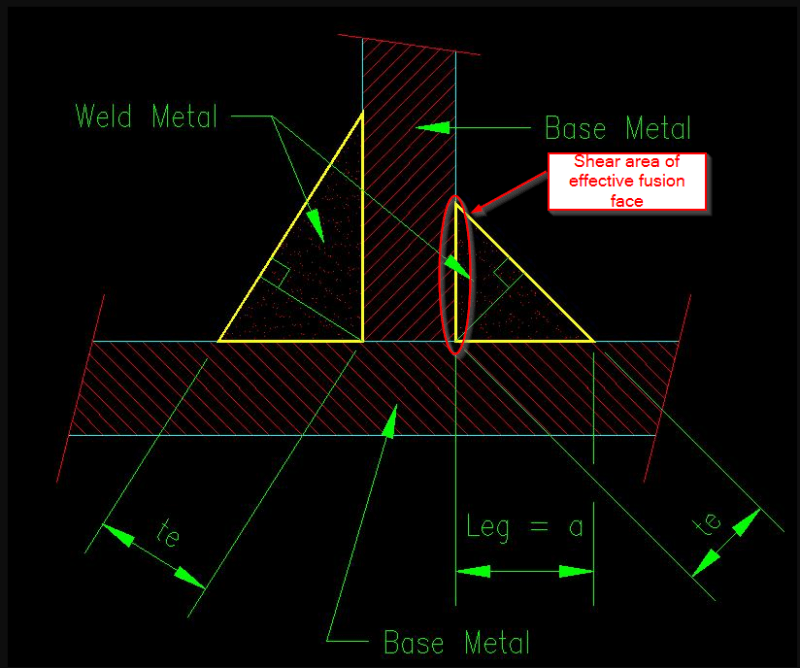
From my understanding, fillet weld size = leg size = thickness of effective fusion face of base metal.
2021-09-09_13_39_02-Window_eyvsjp.png


So it would be:
Linear Resistance to Shear in a Fillet Weld (Base Metal): fw2 = (0.67 * 0.67 * Fu) * (dw) (Unit of Force / (Unit of Weld Length))
 
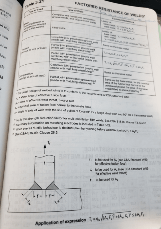
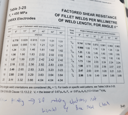
Excuse me if I have missed something obvious (been a long day of work + taught for 4 hours + took a course of my own) but is not everything you are asking outlined in Tables 3-21 and 3-25 of S16?

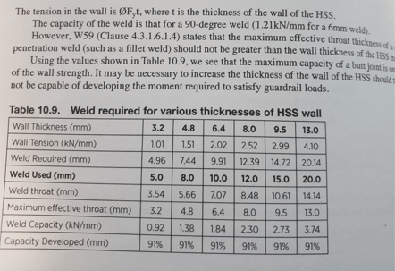
For conservative estimates of fillet welds (which I also use all the time even as a fabricator) I simply use 0.933 kn/mm for 6mm fillets and ratio based on leg size for anything else. Also, to develop HSS section strength via fillet you can find a table in "Structural Steel for Canadian Buildings: A Designer's Guide" that correlates leg size to HSS thickness to develop it (I can post it later if you want, it's at the cottage right now so I don't have access).

Pic_1_jfwynx.png


Pic_2_ho9nw8.png


CWB (W47.1) Div 1 Fabricator
Temporary Works Design
 
Blodgett goes through an allowable stress method to do this.

My understanding of what you are after is finding the minimum size fillet weld to develop a plate in shear/tension. I've always formulated it as the leg size versus a constant x Fy/Xu x thickness. Go through the exercise it seems like you might be there, but I don't feel like tracking errors in this thread.
 
I would think Blodgett is old enough to be proper allowable stress, so plastic modulus wasn't used (though I didn't bother to check).

For the bending case, you could use utilisation * shape factor (plastic/elsatic modulus), up to a maximum of 100%.
 
skeletron said:
I've always formulated it as the leg size versus a constant x Fy/Xu x thickness. Go through the exercise it seems like you might be there, but I don't feel like tracking errors in this thread.
Thank you! This is very similar to what I was trying to achieve. I was wondering initially if others had used a formula like this, glad this is the case!

enable said:
Also, to develop HSS section strength via fillet you can find a table in "Structural Steel for Canadian Buildings: A Designer's Guide" that correlates leg size to HSS thickness to develop it (I can post it later if you want, it's at the cottage right now so I don't have access).
Ok thanks! That looks good enable. I would be glad to check this reference.
 
steveh49 said:
For the bending case, you could use utilisation * shape factor (plastic/elsatic modulus), up to a maximum of 100%.
(plastic section modulus)/(elastic section modulus) would only be used in the situation where we would have a class 1 section?
 
Hi Logan82

A lot of good info on posts given to you here👍

My take on fillet welds is that I have never used software for the calculations and always done they by hand. My understanding is that the fillet welds will usually fail in shear across the throat thickness, that’s the line drawn from the hypotenuse of the weld at ninety degrees to the hypotenuse and intersecting the lines of the opposite and adjacent lines of the fillet triangle. I tend to treat welds as lines and use the geometric shapes like a square,round,I section to get an average stress because the stress distribution in welds is very complicated. The throat thickness I refer too is the dimension marked te on your diagram, to me that’s the shear area to be considered for weld failure.

“Do not worry about your problems with mathematics, I assure you mine are far greater.” Albert Einstein
 
Design of Welded Structures by Blodgett is probably the best engineering book I own.

From the AISC 14th Steel Construction Manual:
For a longitudinally loaded fillet weld with 70 less than or equal to 100 times the weld size in length (and using 70 ksi electrodes) the available shear strength is

ϕRn = 1.392*D*L where
D = weld size in sixteenths of an inch
L is the length

Ex: For a 3" long 1/4" fillet (i.e. 4/16" fillet), ϕRn = 1.392*4*3
 
Status
Not open for further replies.

Part and Inventory Search

Sponsor