Eng-Tips is the largest engineering community on the Internet

Intelligent Work Forums for Engineering Professionals

Easy way to fix binding? 4

Status
Not open for further replies.

MechvsManu

Mechanical
Mar 20, 2024
24
0
1
CA
I have a welded frame with 4 Festo air slides to lift a product. It's worked fine for months but now seems to bind and jamb more and more. I've had maintenance do all the usual suspects - oiling, check air line, etc.
I'm assuming because it's a weldment that the cylinders are just fighting each other due to misalignment so my solution is to replace the bolts with shoulder bolts that will give the cylinders a chance to move a little and hopefully solve any binding issues.

Is there something basic I'm missing?
Screenshot_2024-07-12_075408_knztl2.png
 
Replies continue below

Recommended for you

I would consider removing one of the actuators and relocating its mate to the center of the beam for a 3 point lift. Think of a table on an uneven surface. It wants to rock. You should avoid 4 points of support when possible.
 
OP,
From the drawings, I am assuming the frame is lifting an unbalanced load. I am also assuming the actuators have linear guide bearing. I would suspect the linear guide bearing were overloaded from the start and it just took so many cycles till they were deformed to the point to cause binding. Moving forward, I think you need to assess the forces caused by unbalanced loading and install the needed guides to resist those forces, so the lifting system (actuators) can work independently from the suspension system.
I may be totally wrong but that's what I see from looking at your drawing, making the noted assumptions and doing no calculations.
 
OP
not enough information so educated guess
The design needs braces. To reinforce
Top and bottom frames. At each corner
To prevent the
Lifts from over load , a four bar arrangement.
It should help keep the lift from deforming.
Rough sketch to follow.
Comments from others if I am wrong. Is
Appreciate.
 
You have a classic situation here. Misunderstandings the functions of linear bearings and fluid actuators contribute to poor system design. Two bad assumptions here:
1) The motions of multiple "uncontrolled" pneumatic actuators that appear identical will be synchronized. Wrong.
2) Linear bearings prevent binding.

1) The motion of any individual pneumatic actuator is affected by the timing of the signal, the amount of input pressure, the setting of any flow-restrictive speed control device, and the amount of internal friction. In a multi-cylinder system ANY mismatch in any of those parameters will result in mismatched speeds.

2) Linear bearings CANNOT overcome mismatched actuator motions, or the resulting binding condition.

Pneumatic actuators should be used as ACTUATORS only. Not SYNCHRONIZERS. They can provide the force, but they are very poor controllers of speed. That is the source of your binding.

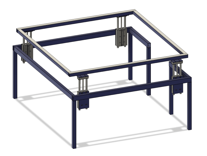
You need some additional mechanism to insure that all four posts move at the same time and the same speed, regardless of the location of any actuators. One way to do that is with a rack and pinion arrangement. Picture this: a single shaft with identical pinion gears mounted on each end. Those two gears are each engaged with linear racks. As the shaft rotates both racks will move - simultaneously. The shaft does not have to be powered. It just has to engage with both racks. Neither rack can move without the other one moving with it. You can achieve the same synchronizing function using roller chain as your rack.

That takes care of two posts. There are several similar methods of synchronizing the motions of two pairs of posts so you have four moving together.

This will prevent binding.
 

Your assumptions are correct, the loads differ from unit to unit but are all unbalanced. Maybe a 300lbs load and each cylinder is rated for 300lbs.
The actuators have integrated linear bearings in them.
You could be right about the overloading of the cylinders, although there is no noticeable deformation on any of the cylinders using a square - it could just be very slight though.
 

The frame isn't moving or bowing at all. The cylinders just seem to not all lift at the same time and sometimes this cause it to get stuck halfway up. With a bit of a manual lift it complete the move. I don't think braces are the problem.
Are you suggesting a 4 bar linkage at each corner?


1) the cylinders all have flow controls but the accuracy is questionable at best. They seem to lift at the same time with no load but that will obviously change when there is a load added.
2) You're right, I thought we could get away with a cheap solution as we didn't care if it lifted perfectly evenly or not.

I agree with the points you made. We were pretty overpowered with the lifts so I thought it would lift relatively smoothly (adjusting flow controls to get them all to lift evenly).
A rack and pinion might just be the way to go, I initially wanted to keep chains out of it due to the proximity of people crawling under there but I can easily guard it if need be.
 
OP,
I am guessing you are feeling the general consensus that there is no easy way. I understand that you are trying to salvage your design but no offense, but it appears you tried to reinvent the wheel by making it square and now are trying to figure out why the ride is bumpy. I am never above copying someone else's design (outside of legal considerations). Consider a mechanics lift, there are rack and pinion, chain lift, scissor type and my favorite as a kid, just one fat cylinder in the middle. I don't think your original approach will get you where you need to be. A book I like to go back to for ideas is:
 
http://160592857366.free.fr/joe/ebooks/Mechanical%...[/URL]]

I fully agree with you about copying an existing design. I am in no way above that either. I should point out that the above design is for a very specific purpose. The product is set on top of the table, then the table is lifted 8", and 2 people stand inside the table and check the container for defects. So a scissor lift or one fat cylinder in the middle won't work. If there was a simple off the shelf solution I'd just buy that but I'm also limited with space around the frame, we have about 30" and we need room for people to walk past so I can't get any bigger of a footprint.

Thanks for the book though, looks like a useful resource.
 
Are these pneumatic or hydraulic?

Nevermind - I see they are pneumatic, which means flow control is for rate not for position. You need to have position measurement on each cylinder and a control system to keep them in sync. It can be done mechanically with torsion bars and levers and valves or electrically with LVDTs and a controller.
 
Mech
Ever used an automobile jack stand. Or a transmission lift.
The automobile is lifted with a hydralic jack.
Then a jack stand is slid under a hard point.
It is then adjusted by sliding up the member.
Then a pin us slid in place to prevent movement.
Make four post, one at each corner. Use a portable lift , then when the correct hight is achieved. Slide pins in each corner. Then lower and remove the hydraulic lift.
 
OP,
Given your design constraints a couple ideas that "might" get you where you need to be. First, consider decoupling the top of the actuator from the frame, to allow for lateral movement in both x and y planes and allowing rotational movement around the same axis with backets to prevent extreme movement. Second, consider adding a plate or brace as second point of attachment for your actuator to make it more rigid because any body or frame flex is going to jamb you up.
rzobz4so_zphmfh.png
 

I get your first suggestion. I oversized the holes on the top plate and used shoulder bolts to give the top plate movement in X and Y like you suggested. I also have some shoulder bolts for the actuator body so they have some room to pivot.

For your second point are you saying to reinforce the actuator body to make it more ridged?
 
OP,
Yes. Consider degrees of freedom and how an actuator, that can pivot about a pin in only one plane, is going to affect the rest of the system. Rigid mount, all your actuators are now acting in the same direction.
 
Heaviside1925

I feel like rigid mounting of the actuators may be a part of the problem. Due to the welded plates(actuator mounts) on a welded frame, I feel like some of the cylinders may be off in the Z direction by a degree or two, so they're going "up" in slightly different planes and fighting each other.

Does that make sense?
 
1. It is always nice to ask the folks who are using and maintaining the equipment for their input. It creates good will. Are these people stumped and turning it back over to you?

2. Has Festo provided any suggestions?

3. I am a fan of fully constraining one corner and letting the other corners have some float.
 
We don't know the size of this thing, or the loads.

It looks very flexible to me.

If it "worked fine for months" but now doesn't, that tells me that the bushings in the cylinders have lost their long-term fight against constraining the flexibility in the system and now things are binding because there is too much angle between guide rods and bushings.

You're letting people work under this load supported only by air pressure? Has your safety department given the OK for this? Do you have a safety department?

You're letting people work under and around this lift that looks to have a clear crush point when it comes down? Has your safety department given the OK for this? Do you have a safety department?
 
Status
Not open for further replies.
Back
Top