Continue to Site

Eng-Tips is the largest engineering community on the Internet

Intelligent Work Forums for Engineering Professionals

  • Congratulations SSS148 on being selected by the Eng-Tips community for having the most helpful posts in the forums last week. Way to Go!

Economical Column Design (Rule of Thumb) 3

Status
Not open for further replies.

struggle67

Structural
Mar 29, 2013
116
Hi

I am new to columns or any vertical member design. I only know some of the basic theories.

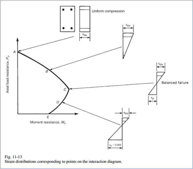
Let’s say I am free to choose whatever column size I want. May I know based on your experience, where is the most economical point (NEd, MEd) on the column-interaction diagram? Reinforcement ratio? 2%? And why?

Thanks, and Best Regards,
 
Replies continue below

Recommended for you

Columns with minimum moment:

For Stocky columns 0.5*f'c at Le/r=20
For Slender columns 0.4*f'c at Le/r=35 ; 0.3*f'c at Le/r=45 ; 0.2*f'c at Le/r=60 and 0.05*fc at Le/r=100


Effective Length (Le) = Length * K-fixity factor. Conservative to assume k=1.0.
Radius of Gyration (r) = sqrt (Imin/A) or 0.3*min dimension for rectangular and 0.25*radius for circular.


Like so many simple questions, the answer is complicated.

Given that reinforcement is expensive, choose a column size where the reinforcement needed is the bare minimum. Of course, there are code-required reinforcement and detailing minimums for ductility. The higher your seismicity, the more additional requirements there are

If possible, you want to make your column sizes as uniform as reasonably possible and vary the reinforcement where additional capacity is needed. Consult with local contractors as to which nominal sizes have standard formwork available.

Round columns are probably the most "efficient" for axial-load-dominated columns, but round formwork and spiral ties can be expensive.

One of the biggest gripes from the field is the congestion of the rebar where the girders connect into the columns. A few big bars in the girders and a few big bars in the columns can make rebar placement a nightmare. Or an impossibility. If you sketch the bars to scale you get a sense of whether or not your joint is constructible.

High strength concrete gives you, well, high strength columns. Know what materials are available in your region and specify them appropriately. You can spec different strength concrete for columns than the floor framing, but you better have excellent quality control to make it happen.

I worked on a hospital where the bulk of the columns were 20"x20" with (4) #9 bars. Exactly 1% and just 4 bars in the columns. It doesn't get more efficient than that.
 
I worked on a hospital where the bulk of the columns were 20"x20" with (4) #9 bars. Exactly 1% and just 4 bars in the columns. It doesn't get more efficient than that.

Just be aware most codes would have limits on the spacing of reinforcement on each side of the member and on the minimum number of longitudinal bars (usually more than 4). The rules are there to ensure good ductility and confinement. So make sure you follow all your local rules. Start typically by satisfying all the detailing provisions for your chosen column size and then increase bar size until you satisfy the strength requirements. If you predominantly have flexure in one direction, then varying the bar size first on the compression amd tension faces is obviously more efficient. Having different sized bars in different locations is relatively easy. But too many changes makes the chances of getting something wrong on site more of a prospect.

One thing I've noted in the past is the amount of reinforcing going into the stirrups can be significantly more than you expect, but people concentrate on longitudinal reinforcement only when optimising. Sometimes for heavier columns your confinement reinforcement may be greater than 50% of the total reinforcement by weight. So don't forget to review that.
 
Trenno:
Great rule of thumb... been around for 50 years that I know of...

Rather than think climate change and the corona virus as science, think of it as the wrath of God. Feel any better?
-Dik
 
Hi Thanks Everyone,

Trenno, Thanks That will surely useful for me later on.

I am also curious that in the interaction diagram below is point C considered better / more efficient than points B & D due to this enhanced moment capacity?

Picture1_t4ylwl.png
 
Chasing point C (which I believe is what you meant) will usually create false economy if column formwork sizes change and layout becomes more complicated.

----
just call me Lo.
 
I believe forum member IDS produced the following chart (AS3600).

Notice how slenderness effects kick in at Le/r = 20.

Untitled_picture_hox5qj.png
 
OP said:
I am also curious that in the interaction diagram below is point C considered better / more efficient than points B & D due to this enhanced moment capacity?

Much depends on how you're defining "better" and "more efficient".

1) [C,D,E] are better than [A,B] from an engineering and safety perspective because values below the balanced point [C] will produced a more ductile failure mode not governed by rebar yielding rather than concrete compression failure. This may be of enhanced importance in situations of high seismic demand.

2) [E] is basically a beam rather than a column and in many instances, I would consider that economical and spatially inefficient.

3) In the lower stories of a high-rise building where moments become negligible relative to axial demand in gravity columns, I feel that even being as low as [C] on the graph represents economical and spatial inefficiency.

Like others, I feel that formwork and congestion concerns dominate concrete column economy.

As far as I'm concerned, circular columns are for architects. The circular bar pattern always seems to cause congestion issues for me. If I'm not overly concerned about confinement issues around the outside of a circular column, I'll usually just stuff a square cage in there.
 
Trenno said:
Columns with minimum moment: For Stocky columns 0.5*f'c at Le/r=20...
Does this mean that the axial capacity of a minimum moment column is 0,5*fc'*column_area for Le/r=20?

 
I've got a related question that would fit in well here although it will be kind of an ugly ask.

I have a printout of an amazing concrete concrete design spreadsheet prepared by another firm which I cannot share. It does pretty much an entire high-rise building with detailing, shear stud reinforcing etc. I would not feel comfortable calling them up and asking about the inner working of their intellectual property.

The most interesting part of the spreadsheet, to me at least, is that it seems to deal with preliminary design very handily. There's a bit in the documentation where they basically say "If Mb < 2.5 MPa, don't sweat the reinforcing, something will work. This confirms that the column size will be adequate and the reinforcing can be sorted out later". If you think about the work flow on a typical high-rise concrete building, this is a hugely powerful tool if it's legit. Nobody cares what the rebar is early on but being able to dial in sizes for your architect with minimal effort is a big win. Trouble is: I don't know anything about this 2.5MPa method. The spreadsheet setup suggests that Mb = Moment / Section modulus. That makes sense to me but why 2.5MPa should be a reasonable limit is not apparent to me.

Anybody know anything about this method? Maybe it comes from some ancient text book or ACI paper I don't know of? Part of what may make this difficult to parse out is that the 2.5MPa is in metric units and may well be a modified version of something else that would have been expressed in imperial units that would probably be easier to identify.
 
You want to keep the same column size for 3 or 4 floors, and not change each floor, or keep the same size.

Rather than think climate change and the corona virus as science, think of it as the wrath of God. Feel any better?
-Dik
 
I'd say it just results in an infinitesimally small moment.

For example for a 600 x 600 column the 2.5MPa limit calcs out to a moment of 90kNm. Minimum steel would probably net you several times this, and if subject to any seismic loads or gravity loads with any sort of reasonable beam span 90kNm would be quickly exceeded.

I'm not aware of anything formally noting this type of thing. But it sounds more like a best practice/experience limit they have found?
 
I feel that the 2.5MPa makes a lot of sense when you actually think about it and compare it to Trenno's guidance. That's likely going to be pretty close to 0.1fc' for moderately slender columns and if you end up with a highly slender column, you go up to 50 or 60 MPa and then you're at the 0.05fc' intent.
 
Agent666 said:
But it sounds more like a best practice/experience limit they have found?

Thanks Agent, you may well be right about that.
 
KootK said:
If Mb < 2.5 MPa, don't sweat the reinforcing
For rectangular columns:
M/(bh2/6) = 2,5 MPa
M/(bh2) = 2,5/6

Since non-dimensional moment mi = M/(bh2fc)
M/(bh2) = mi*fc

mi*fc = 5/12

If concrete of 30 MPa is used (around 4 ksi) and partial factor of safety is 1,5 (design strength is 20 MPa):
mi < 0,02

Isn't this very low (for higher concrete strengths, this moment is even lower)? Looking at an interaction (Moment - axial force) diagram, this seems like an area with less than minimum reinforcement.

Or did I miscalculate something?
 
jayrod12 said:
...and if you end up with a highly slender column...

Thanks for your contribution. The documentation does, in fact, start off by saying that most of the columns in their typical building will wind up being slender. You know the drill in the residential towers: 300x, 250x, 200x. The dreaded slender wallumn that will persist until explicitly prohibited.
 
hardbutmild said:
Isn't this very low (for higher concrete strengths, this moment is even lower)?

It is. To be honest, the setup is opaque enough to me that I may well be missing a 12 x multiplication somewhere or something. So I'd like to not get too caught up on the particular values. I'm really just interested to know if there are any good sizing methods out there that do account for significant moments and slenderness. This is the first that I've seen. And it may well be that it's just hugely conservative. Based on the work to which this setup would typically be applied, the moments would generally be quite small relative to the axial demand as they would be mostly just slab moments modelled with very liberal estimates of column stiffness.
 
Maybe the 2.5 MPa is an approximation to flexural tensile strength and therefore minimum bending strength. 2.5 MPa = 0.6 * sqrt(2500 psi).
 
Status
Not open for further replies.

Part and Inventory Search

Sponsor