Eng-Tips is the largest engineering community on the Internet

Intelligent Work Forums for Engineering Professionals

Edge Beam Support Condition

Status
Not open for further replies.

YC611

Structural
Oct 12, 2023
14
0
1
US
Hi all,

I would like to know how would you assume the supports of the steel edge beam in the following situation (Ignore all the loadings for now):
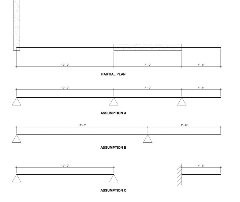
Beam left end pocketed in load bearing wall, right end is free, a 7'-0" of load bearing wall as intermediate support.
Can someone point to the correct direction? Any resource will be helpful. A design example will be even better.
SKETCH_1_ewceby.jpg
 
Replies continue below

Recommended for you

It depends on how you detail it more than anything. You can choose how it acts.

For the 7'-0" support, are you going to anchor it continuously into the wall, or only in one or two spots? Is there wall above the beam at the intermediate support? If those are the cases, then I would imagine it would be more of a fixed connections.

If it is bearing on top of a wall, with anchorage only on each end (no intermediate anchorages), and minimal load on top, then I would model it as assumption A.
 
Thanks for your response. That is exactly what I needed!

My original design is to have anchorages only at the two ends of the 7'-0" wall. however, I do have a load bearing above the beam as well (this is 8" fully grouted CMU wall, 11'-3" per floor, 45'-0" height in total, so this weight is not minimal).

I will redesign accordingly with the actual loads and am going to provide the continuous anchorage in this case since I want the wall loads to only go to the wall.

Once again, thanks for the explanation!
 
To be clear, I would anticipate it to be more like option C. Both ends of the beam extending out of the 7'-0" support should be designed as fixed with that much load bearing on top of them.

How do you plan to transfer out of plane and in plane loads through the steel beam and into the foundation from the wall above? You will need to detail this out as well. 45' of CMU resting on a cantilever beam seems like a recipe for disaster. How do you plan to provide out of plane stiffness for this cantilevered portion?

You don't have to give me an explanation of your structure by any means, I am just pointing out some of the big ticket items I see.
 
I am happy to include the missing information.

The 7'-0" wall is one of the shear wall which will deal with the in-plane loads itself with rebar. Rebar will run through the beam flanges to reach the development length.
The cantilever beam is only at the and 4th floor, the lower floor has longer span of CMU shear walls. (Sorry if I mislead you to think that the steel beam will be supporting the entire 45' of CMU wall)
I have 2 more shear walls of same direction in other locations which are not shown in the sketch.

The out of plane loads will be resisted by the diaphragms and shear walls (2 side walls, which are also 8" CMU walls).

So basically everything will still get transferred down to the foundation.

I really appreciate your help and your general concerns about the safety.
 
OP said:
however, I do have a load bearing above the beam as well

OP said:
The 7'-0" wall is one of the shear wall which will deal with the in-plane loads itself with rebar. Rebar will run through the beam flanges to reach the development length.

My answer would be that you don't want to do this. This condition would set up a terrible, and unpredictable, prying mechanism between the beam and the CMU. And that could potentially damage both the beam and the CMU. I feel that you need a different, overall scheme for this.
 
Hi Kootk, unfortunately, the contractor is up to the 3rd floor now and the client wants this to happen so they could have a huge corner window like the one below.
corner_window_p00iwq.jpg


I was just informed of this yesterday, so I have to come up with a solution to control the damages. I have told the contractor to not start the beam until I give them a remedy.

Or would you say to give up this shear wall and reanalyze my other two shear walls to see if they are able to handle the lateral loads?

Also, what kind of mechanism would you say is the potential hazard?
 
OP said:
Or would you say to give up this shear wall and reanalyze my other two shear walls to see if they are able to handle the lateral loads?

Meh, I'm not overly worried about the shear wall function.

OP said:
Also, what kind of mechanism would you say is the potential hazard?

See the sketch below that I struggled mightily to draw in a persuasive manner. Basically just the effects of the prying action that I mentioned previously.

OP said:
Hi Kootk, unfortunately, the contractor is up to the 3rd floor now and the client wants this to happen so they could have a huge corner window like the one below.

It is a cool window. And a smaller scale thing that I was envisioning. Might be alright.

What is your beam size? Stiffness is your friend in this for sure.

c01_yhld3z.png
 
Kootk, thanks for the sketch, and I agree with you. I thought about that when I asked about the support conditions. This is a residential building in NYC, a typical 20' width building.
Currently, the main load is the CMU wall itself and the window dead weights. The beam size is at W12x30 now.

Wrantler, that is not an option, and I do not trust this contractor at all if you must ask me.

He has made all sorts of changes by himself and his interior designer without notifying us. He did not schedule the inspection with us until recently and there are just so many wrong things in this building and more to find out after I visit the job site next week.
 
Status
Not open for further replies.
Back
Top