Eng-Tips is the largest engineering community on the Internet

Intelligent Work Forums for Engineering Professionals

Edge distance vs material thickness 2

Status
Not open for further replies.

PJYDE

Aerospace
Feb 26, 2018
20
0
0
NL
Hi all,

Just a generic theoretical question:

There is a general rule that the edge distance of a fastener should be at least 2 times the diameter of the fastener (measured from the center of the fastener), even better when adding a tolerance value on top of the 2D value.

Imagine a joint of 2 layers of 6061-T6:
- thin skin 0.025"
- thicker support structure 0.125"

I assume the 2D rule is fare more important for the thinner skin?
Is there documentation regarding edge distance that considers material thickness?

Many thanks for your reply in advance!


Replies continue below

Recommended for you

For a thick part with short edge margin, you could consider whether a lug analysis might be an appropriate means of characterising the static strength & durability for the detail. In terms of fatigue, considering the Kt for an open hole near an edge, I recall the variation stress concentration is fairly insignificant until e/D becomes very much less than 2.0.

Consider also from a DT perspective that a corner crack in an Al part will develop the majority of its life growing from an initial flaw to thru thickness, after which the increased growth rate usually means the remaining life through to critical crack length is relatively short.

Whilst metallicnairframes usually work to 2d, in some other applications a much lower edge margin rule of thumb is employed.
 
Is there documentation regarding edge distance that considers material thickness? - short answer, no. There might be some company proprietary test data somewhere, but unlikely to be anything public.

Is this for initial design? or an MRB repair? or in-service repair?
Is this for a fatigue critical part? a part required to comply with DT requirements?
Are you using MMPDS allowables? (IIRC there is usually static bearing allowables for e/d=1.5 in MMPDS).

BUT, as noted above, with very short edge margins you have to carefully consider fatigue, and also consider that the critical failure mode could change from the desired bearing mode to something else.

And if this is for new design, an edge margin < 2 (+tolerance) is going to screw over the poor MRB or repair engineer that has to deal with an even shorter edge margin.
 
if you have a production report (and MRB or an RNC/NCR), then the stress guys will probably buy a short eD in the 0.025" sheet since there is the 0.125" thk underneath (supporting the thinner sheet). Of course, there's a sum involved, but probably ok.

Of course you could use the 1.5 eD bearing values from MMPDS (as opposed to the 2 eD values ... this is where the "2eD" rule comes from) for the thinner sheet (in conjunction with the 2 eD for the thicker plate) ... just depends on how much calculation you want to do.

And as above, you shouldn't design to 2 eD ... 2 eD + 0.05 is typical, to give some tolerance for mislocation of the hole.

"Hoffen wir mal, dass alles gut geht !"
General Paulus, Nov 1942, outside Stalingrad after the launch of Operation Uranus.
 
It is not about a thinner part or thicker part edge distance. The issue is which part is having lowest bearing allowable value as per design and which part is affected in your NCR. Need to re-evaluate the NCR bearing allowable value with the reported edge distance and check it is far above the Design bearing allowable. If not compare it with actual test load data.

Hope this will help you.
 
well, OP does say "2 layers of 6061-T6".


"Hoffen wir mal, dass alles gut geht !"
General Paulus, Nov 1942, outside Stalingrad after the launch of Operation Uranus.
 
Presumably, the thick sheet is the load-bearing member... and the thin sheet is 'fluff'.

Also, an unknown is 'how many holes'??

Also and unknown is type of fastener...screw [clearance fit]... Hi-Lok in clearance or net-fit... or Hi-Lok in light-to-high interference-fit... or solid rivet in a forged-interference-fit... ETC.

Presumably, the 2D edge margin is based on hole-DiaX2... measured from the local-edge to D-hole center [often with a small +dimension for variability, such as 0.02 to 0.06].

So the real issue is what is the thin sheet metal there for? important, unimportant, permanent, removeable, etc?

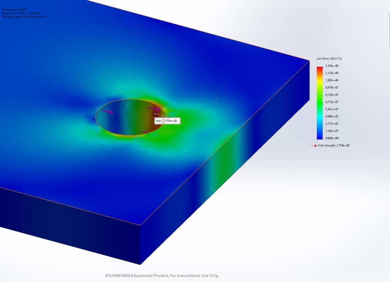
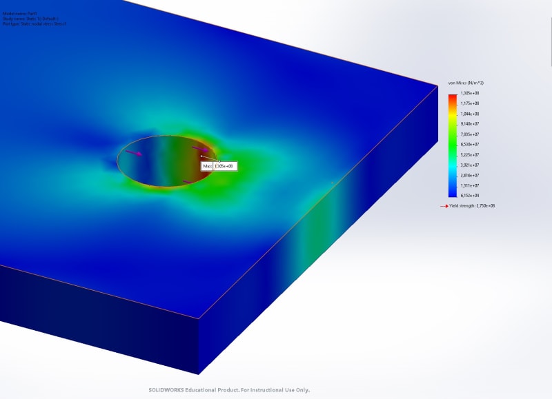
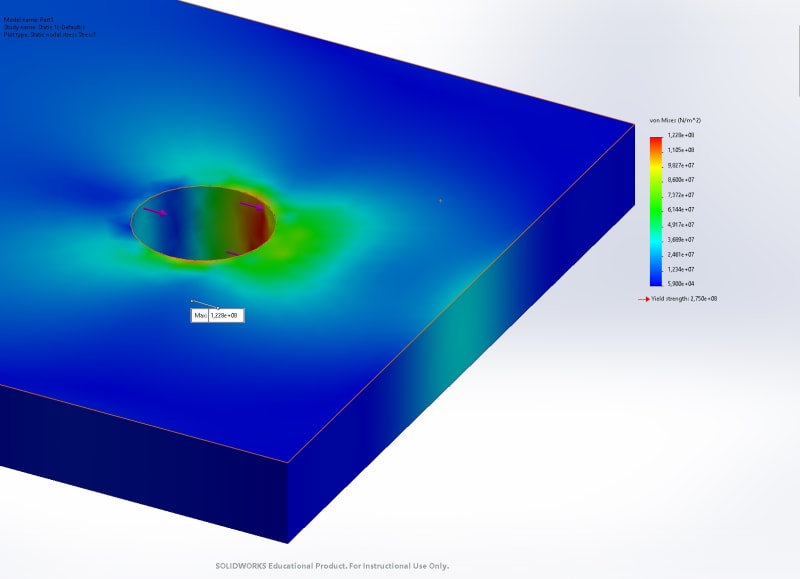
So considering the thicker load bearing sheet... 1.5D(min)-to-2D+ is generally important for free-hole stress concentrations** one-hole or multiple holes can make a difference.

Another sneaky factor is that with shrinking ED, the effects of interference within the hole generates a strain field that can bulge the edge. Also the type of interference... bucked-rivet or solid-shank press-in are worlds apart for installation thru-the-hole strain/abuse. A squeezed rivet is almost perfectly radial. A bucked rivet is mostly radial but the bucking forces/vibration can be abusive in various ways. However solid-shank fastener interference by pressing it into the hole... creates high drag/light scoring on the progressively swelling hole wall - even when installed perfectly straight. However if solid shank fasteners are pressed-in off-angle in addition to very harsh thing in a perfect install, the off-angle can bell-mouth the hole before hiding-it [tight in the middle, loose on both ends, scored, etc]. Obviously every issue with fastening gets worse with shrinking edge margin... where there is less and less metal available to resist to fastening effects.

I have seen min ED expressed in various ways for various reasons... and anything less that 2.0D [typically +0.03/-0.00] creates unexpected issues/complications when everything is hand-assembled... far-less-so for automated Assy.

NOTE1. The very best reference for 'stress concentrations' I have ever had the pleasure to know about... wink-wink-wink...secret to be revealed... 'Peterson's Stress Concentration Factors'... now in an impressive/expanded-content 4th Ed. I have had a second edition for decades... but recently 'stumbled-on' the 4th Edition in my company's on-line Library service [Knovel]. Dang... started flipping pages like crazy... absorbing the new content.

Regards, Wil Taylor
o Trust - But Verify!
o For those who believe, no proof is required; for those who cannot believe, no proof is possible. [variation, Stuart Chase]
o Unfortunately, in science what You 'believe' is irrelevant. ["Orion", HBA forum]
o Only fools and charlatans know everything and understand everything." -Anton Chekhov
 
Thanks for your comments.

I did a simple static SolidWorks simulation, this does show that ED has a greater effect on the thinner member of the joint.

Results_i6uman.jpg

1_njvjxx.jpg

2_yljhqg.jpg

3_cntz7x.jpg

4_px8esw.jpg

5_upnhk1.jpg

6_xnvclr.jpg
 
Well, then the theoretical answer remains "no, there is no published data". And a FEM is unlikely to correlate to actual strength data (I've been down that road into the swamp).
 
the only reason to worry about the 0.025" sheet, compared to the 0.125" thk sheet/plate, is if the load is coming from one element into the other. Then obviously the 0.025" sheet is critical. Otherwise, if the 0.025" sheet is "supporting" the 0.125" plate, then the 0.025" is irrelevant ... ok, not irrelevant but a very small part of the solution. Low eD on the thin sheet would reduce the small load that the thin sheet can carry, compared to the thick plate. Probably easiest is to ignore the thin sheet altogether.

"Hoffen wir mal, dass alles gut geht !"
General Paulus, Nov 1942, outside Stalingrad after the launch of Operation Uranus.
 
I am seeing fastener bearing in the FEM... but no fastener RADIAL interference [hole compression] stress/strain.

Regards, Wil Taylor
o Trust - But Verify!
o For those who believe, no proof is required; for those who cannot believe, no proof is possible. [variation, Stuart Chase]
o Unfortunately, in science what You 'believe' is irrelevant. ["Orion", HBA forum]
o Only fools and charlatans know everything and understand everything." -Anton Chekhov
 
Status
Not open for further replies.
Back
Top