Continue to Site

Eng-Tips is the largest engineering community on the Internet

Intelligent Work Forums for Engineering Professionals

  • Congratulations SSS148 on being selected by the Eng-Tips community for having the most helpful posts in the forums last week. Way to Go!

Effect of a cut on structure load distribution 3

Status
Not open for further replies.

Aptx4869

Mechanical
Mar 1, 2018
44
Hello Dears

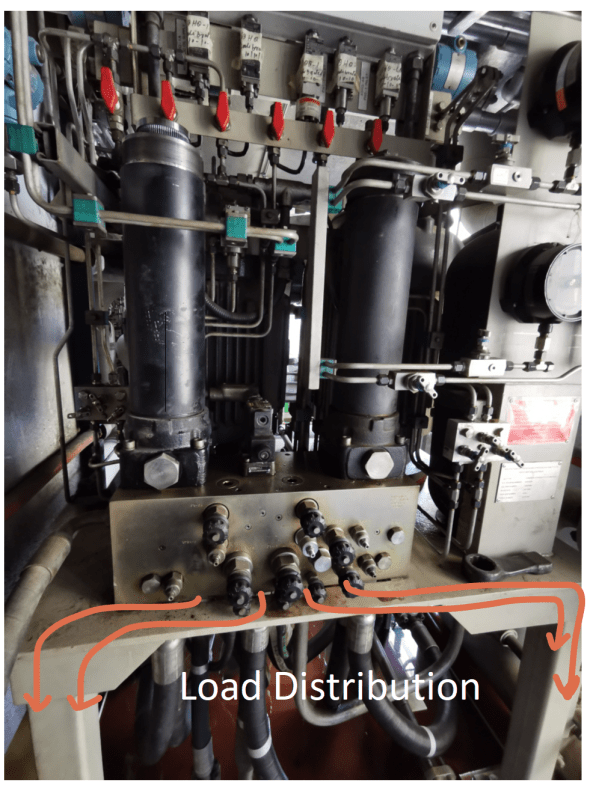
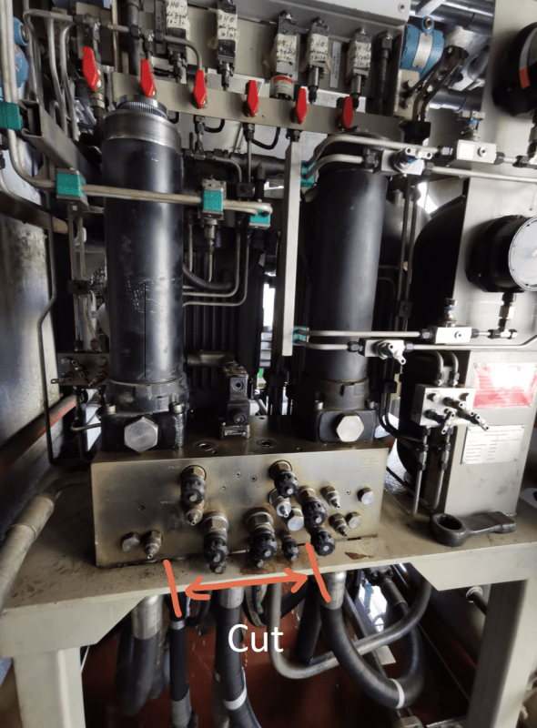
Need your help to evaluate the effect of making a cut in this area (shown in the picture) on load distribution. The reason of the cut to make space for the below valves so we can easily close/open. Will this make load more on some of the columns than the others ?

As I understand, the path of load is shown in arrow in the attached picture.

sketchpad.pro_BDED6FF329F87078627_wwmihb.png


sketchpad.pro_BDED6FF329F87078627_1_kswvs3.png


redes_n9s6tb.jpg
 
Replies continue below

Recommended for you

Will this make load more on some of the columns than the others ?

Just eyeballing it: probably not significantly. Me personally, I'd be more worried about the changes in the stress in that top plate than load distribution to the columns. (A analysis will tell you both.)

 
Thanks WARose

I am mechanical, but I have to make decision on this case because in our plant there is no civil engineer. Also the vendor for this system is not responding.

Is there an easy online tool to make this analysis ?
 
You don't need a civil engineer for this. Even doing an analysis at all is over the top.

If you are really that concerned, measure the deflection in the center of the plate, and use that with the section of the plate (which you know) to calculate stress. It's going to be extremely low.

Then recalculate with your new section after the material is removed. It's going to be extremely low again.
 
Before you cut the steel, I think you will need to weld a steel-plate across the two legs to prevent sway and stiffen the structure. Then cut out the metal.
 
I am mechanical, but I have to make decision on this case because in our plant there is no civil engineer. Also the vendor for this system is not responding.

Is there an easy online tool to make this analysis ?

If (by that) you mean you don't have FEA software....a alternative might be to come up with a simple, conservative beam & column model for this system. You could assume a effective portion of the top plate that resists the loads....and follow the load path from there.
 
it looks like the plate has a cut-out under the "box" ... so you're removing all of the material on the edge.
Does this sound like a good idea ?

I'd add a brace between the two gusset plate (so below the plate level) before cutting, then cut.

another day in paradise, or is paradise one day closer ?
 
Dear rb1957

You are right. The plate has a cut out under the box so that the hoses can be connected to the box. This is why I am concerned.

Thanks for the suggestion
 
Thanks SwinnyGG

Honesty I dont think this gonna work out. During "any" von misses and deflection analysis, you will notice that the part which has highest deflection will have lowest von misses stress. Lowest deflection point will have the highest stress.
 
an 1/8" thick steel plate, welded to the gussets ... she'll be right !
if you want to kill it dead ... use an angle with the flange tucked under the table.

signed,
O'Reilly Structural Alterations and Plumbers

another day in paradise, or is paradise one day closer ?
 
Before you cut the steel, I think you will need to weld a steel-plate across the two legs to prevent sway and stiffen the structure. Then cut out the metal.

Before you weld anything to anything.....you need to know if you can do that. Welding to loaded steel is potentially dangerous.

But there is a lot we don't know here. It doesn't look heavily loaded.....but looks can be deceiving. As much as the OP might not want to.....he may want to get a structural guy involved or (at the least) someone knowledgeable in this area.
 
Is there an way to extend the valve knobs out further or replace with longer-stemmed knobs? Making the knobs stick out further seems easier than modifying the steel frame.
 
Bones206

There should be a way to extend the valve although we haven't started thinking about this option. It will be an option if steel modifications is difficult

But again, since the space is very tight and limited, it will make our work on the valve modification difficult also.
 
can you show us behind the face plate ? where is the horizontal plate loaded ?

is this "table" structure just a façade ?

We're talking about hydraulics here, yes? there can be surprising forces.

option to welding would be bolting a plate/angle to the gussets.

another day in paradise, or is paradise one day closer ?
 
rb1957

I can share it on Sunday. The other side of table mainly have two vertical motors driving hydraulic pumps. The motors are resting and fixed to the table
 
rb1957

Attached photo shows the other side of the structure with two vertical motors.


Hyd_nkxir5.jpg
 
Status
Not open for further replies.

Part and Inventory Search

Sponsor