Continue to Site

Eng-Tips is the largest engineering community on the Internet

Intelligent Work Forums for Engineering Professionals

  • Congratulations KootK on being selected by the Eng-Tips community for having the most helpful posts in the forums last week. Way to Go!

Effect of control cards on the FS curve

Status
Not open for further replies.

VaidehiChennubhotla

Mechanical
Jun 14, 2018
32
Hi,

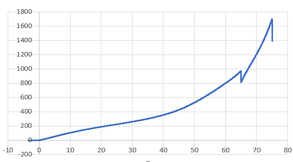
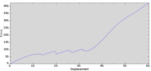
I have a dual layered structure. When a general ILD(Indentation force deflection) test is done on the part, a smooth FS curve is expected as per test data. But inorder to achive convergence, I have used control cards. Does that affect the FS curve?
*Step, name=Step-1, nlgeom=YES, unsymm=YES
*Static, stabilize=0.0008
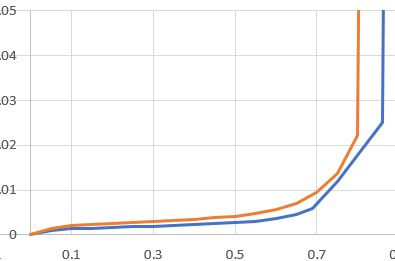
What could be primary causes the FS curve to be wavy ? what can be done to remove this unwanted waviness, is there some control card in input deck which can prevent this wavy FS curve ? It is not the material card because the material card is a smooth curve similar to test data.
wavy_FS_curve_b4nhok.png
test_FS_curve_joars7.png
material_curve_dm9mwi.png
 
Replies continue below

Recommended for you

Hi FEA way,

I reduced the stabilize value from 0.0008 to 0.0003 below that it is not converging. The model doesn't converge when i tried any random stabilize value from 0.0002 to 0.000001
The model I am running is a static compression test so stabilize shouldn't have any effect ? But I have done static analysis previously also. Whenever I used stabilize card, the FS curve has become softer than actual. But this kind of wavy behavior is first time.
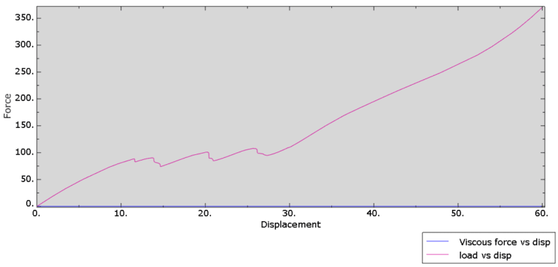
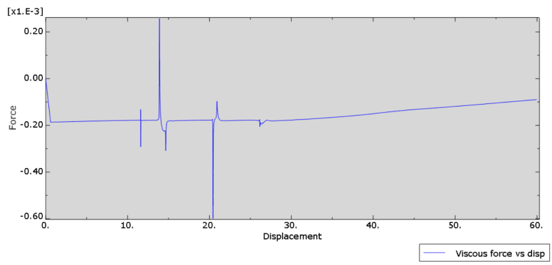
I plotted the viscous force vs displacement , load vs displacement graphs. Looks like the VF vs disp graph is way softer than the FS curve. But the behavior of VF vs disp graph is very strange. Is this genuine behavior ? Also ALLIE seems very stiff compared to ALLSD,ALLCD,ALLVD so I think the dissipation percentage will be way less than 2%. Is there anything that I am missing? How to avoid the artificial damping ?
VF_F_disp_ha3pua.png
VF_vs_disp_njlnpa.png
 
Note that these sawtooth-like parts of the load-displacement curve appear at the same time as peaks of the viscous force-displacement curve. These are the moments when artificial damping is used to help the model converge. But still the viscous forces are very low when compared with overall forces in the model. And, since you say that the ALLSD/ALLIE ratio is also small, then I wouldn't worry about these artifacts. Of course it would be best to make the model converge without any stabilization but this might be difficult in many cases.
 
Try to understand what the solver is trying to stabilize i.e., what sorts of instabilities are occurring in the model at those time points when viscous stabilization is kicking in. For instance, are the load/BCs changing, is the contact status changing, is the material softening, is the structure buckling, etc.?

*********************************************************
Are you new to this forum? If so, please read these FAQs:

 
Status
Not open for further replies.

Part and Inventory Search

Sponsor