Eng-Tips is the largest engineering community on the Internet

Intelligent Work Forums for Engineering Professionals

  • Congratulations waross on being selected by the Eng-Tips community for having the most helpful posts in the forums last week. Way to Go!

Effect of Stiff column elements on raft design forces in CSI SAFE

Status
Not open for further replies.

Ahmad Uzair Arshad

Civil/Environmental
Mar 25, 2021
19
AE
Hi Fellow Engineers,

I was designing a raft for a mid rise 17 story residential tower, It was in my knowledge that Modelling Stiff element under column decreases the max moment because of decrease in clear span.
Even CSI knowledge base acknowledge that modelling of stiff element is a non conservative approach.

[link ][/url]

Anyway, I designed it without col-stiff element & raft is now casted already, Than one day out of curiosity I decided to check the effect of Col-Stiff Element & contrary to my knowledge at some Locations the bending moment values increased by a factor of around 1.5 even at service loads, now my nights are sleepless as this is inducing wide cracks at service & at ultimate cases provided reinforcement is inadequate.

Now theoretically this is not making much sense to me, also I don't see many the engineers use col-stiff approach in design.
Can anyone help me understand, what is happening here.

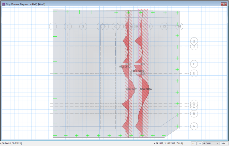
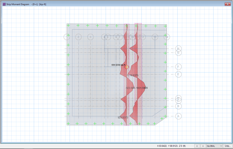
even the bending moment diagram is not making much sense for stiff element model, as bending moment is low under column of larger span.
for model without stiff elements bending moment diagram is more rational.

Thank you
Without_Stiff_members_vulabc.png


With_Stiff_Members_aodtsc.png
 
Replies continue below

Recommended for you

Using Col-Stiff decreases the clear span length, but since it increases the stiffness, it will also attract more of the load. It's hard to tell from the images you posted what the whole model looks like. Did you include all of the columns or just a few to test it out?

Structural Engineering Software: Structural Engineering Videos:
 
Let me try to understand those diagrams.

1) The 1st one is the one that shows us what happens when the rigid zone at the columns is NOT used. Correct?
2) The 2nd one has columns with rigid zones at F8 and F11 as well as E9 and E11. Correct?
3) Your models seem to show pretty similar moment diagrams and results. What values are the biggest concern for you?

I think the issue is most likely related to a relatively tight spacing between column lines 8 and 9 and E and F. What's the distance between each of these column lines?

I would think your design strip shouldn't be totally straight, but should jog between these column lines.
 
ProgrammingPE

All the columns are included, but column stiff element is assigned to only 4 columns, 2 on grid E & 2 on grid F respectively. There is a 6'-0" corridor between these grids.
This kind behavior is only seen in these columns when I apply stiff element to columns of other grids. The moment always decreases but here the moment increases.

I was thinking that the total load is not changing, which means the total reactive pressure from earth should not change since that pressure will be used as load to determine forces inside the raft, the moments diagram should not change.

I mean can we justify this behavior with hand calculations?

The factor of variation of 50% between two models is huge & can have very adverse effects.

Thank you


JoshPlumSE
1) The 1st one is the one that shows us what happens when the rigid zone at the columns is NOT used. Correct?
[highlight #CC0000]YES[/highlight]

2) The 2nd one has columns with rigid zones at F8 and F11 as well as E9 and E11. Correct?
[highlight #CC0000]YES[/highlight]

3) Your models seem to show pretty similar moment diagrams and results. What values are the biggest concern for you?
[highlight #CC0000]if you check in the first model, I have highlighted the value at grid F with cursor. the value is 692 k-ft at (D+L) combination. in the 2nd model the value at the same point is 982 k-ft at same combination the is an increase of 50% in moments [/highlight]

I think the issue is most likely related to a relatively tight spacing between column lines 8 and 9 and E and F. What's the distance between each of these column lines?

[highlight #CC0000]yes it looks like the behavior is because of closer spacing, it's corridor of 6' wide, How can I justify it with hand calculations?
Also Bending moment diagram in the first model make more sense at E9 [/highlight]

I would think your design strip shouldn't be totally straight, but should jog between these column lines.

[highlight #CC0000]yes you are right, I was more interested in forces for column at grid F9 that's why I drew it there [/highlight]


Ahmad -

The challenge is that you've got 2 way bending in the vicinity of those "zigs" in the support locations. That's definitely going to have a bigger effect when you have the rigid zones at the column locations.

It does make a pretty big difference. This isn't something that we can exclusively rely on a computer algorithm to get right. IMO it's going to take some real engineering judgment. Rather than looking exclusively at the strip results, I might take a look at the plate force contours and see what they say for the plate moments in those locations. Ignoring the stress risers that occur directly over the column members and taking the max moments as something closer to what we see at the FACE of the columns. That might give you a better sense of how those rigid zones are affecting the model.

Also, if you think of F8 and E9 as a single (but very long) support for that strip, that might help you understand what's happening. The max moment of 692 doesn't really change all that much. It's more like the location for the max moment shifts from F down towards E.
 
JoshPlumSE-

This is exactly the issue, while designing without stiff members the reinforcement requirement is for Grid E, for which an extra layer of bars was placed,
this extra layer was curtailed according to its development, since the max moment has now shifted from Grid E to F, therefor existing reinforcement at F becomes inadequate for ultimate cases involving lateral forces.

At service loads, cracks of 0.4mm may appear now as per calculations. instead of 0.2mm previously

Now if we use hand calculations for this purpose, I am sure the results would be similar to the model without a rigid zone. Do you agree?

Also, I have rarely seen engineers using a rigid assignment approach for the raft. What is your opinion?

 
I'm not sure what a hand calculation would show. Especially for a situation like this where the line of supports jogs around like that.

I'd be more interested in the plate force contours (especially the ones with the rigid zone). To me that's telling me the "true behavior" of the slab. How to get from those "true" analysis results to an design with bar layouts is the next question.

I put "true behavior" in quotations because all models are imperfect. You've got lots of effects that may not be fully captured (non-linear materials, cracking, etc). The model without the rigid zones is the most reasonable place to start for most design engineers. With the rigid zone model being an incremental improvement.
 
There’s another CSI article on the topic:
CSI Knowledge Base said:
When the option to Include Automatic Rigid Zone Area Over Column is specified, the rigidity of the connection increases, causing deflection and slab reinforcement to decrease. Further, unbalanced moments generally increase, leading to higher punching shear ratios.
While this modeling decision is at the discretion of the engineer, we generally recommend including the rigid zones over column objects.
 
Status
Not open for further replies.

Part and Inventory Search

Sponsor

Back
Top