Navigation
Install the app
How to install the app on iOS
Follow along with the video below to see how to install our site as a web app on your home screen.
Note: This feature may not be available in some browsers.
More options
Style variation
-
Congratulations JStephen on being selected by the Eng-Tips community for having the most helpful posts in the forums last week. Way to Go!
You are using an out of date browser. It may not display this or other websites correctly.
You should upgrade or use an alternative browser.
You should upgrade or use an alternative browser.
Effective length of Equal Angle bracing (welded) 3
- Thread starter mte12
- Start date
- Status
- Not open for further replies.
- Thread starter
- #5
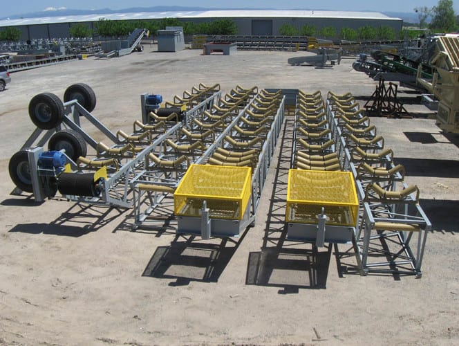
Similar per photo, 3D truss with all angle members.
I think Le, is actually less than 1 if it's welded but difficulty in quantifying. Similar, it there was more than one row of bolts for a bolted connection.
Case I'm looking at needs refinement, that's why I'm asking.

I think Le, is actually less than 1 if it's welded but difficulty in quantifying. Similar, it there was more than one row of bolts for a bolted connection.
Case I'm looking at needs refinement, that's why I'm asking.

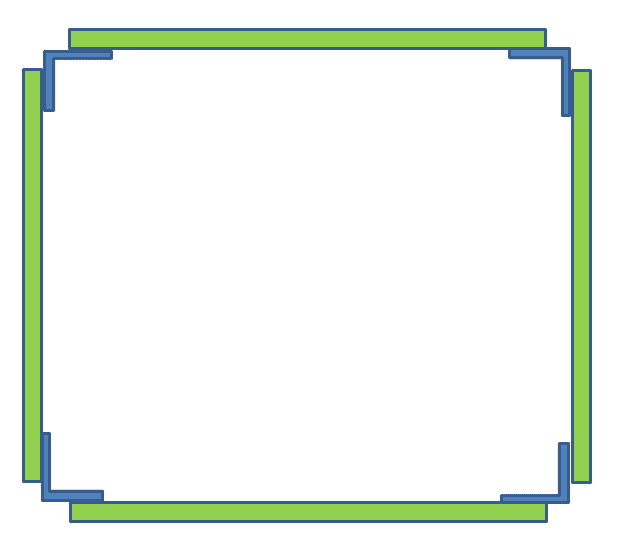
Look like this is pipe support. The majority of the load will be taken by the chord members in the longitudinal direction. Le for chord members, as well as the diagonal bar, will be the distance between panel joints. In the plane shown on your sketch, you need to make sure the presence of intermittent X bracings that are adequate to prevent the in-plane distortion, or you may consider adding stiffener plates at the corners. Note the latter approach is much more expansive to construct, but it may be justifiable to use a shorter Le, measured from the center of weld at one end to the opposite end.
- Thread starter
- #7
Hi, the above is a sample photo only.
The truss is existing.
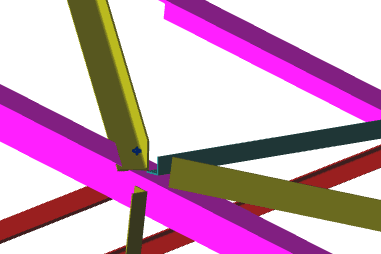
I was going to use the actual length "L" from inner edge of welds (refining as much as I can), and was hoping for a reference which justified "Le" less than 1.0. I'm sure ot depends on rotational stiffness.
The truss is existing.
I was going to use the actual length "L" from inner edge of welds (refining as much as I can), and was hoping for a reference which justified "Le" less than 1.0. I'm sure ot depends on rotational stiffness.
-
1
- #9
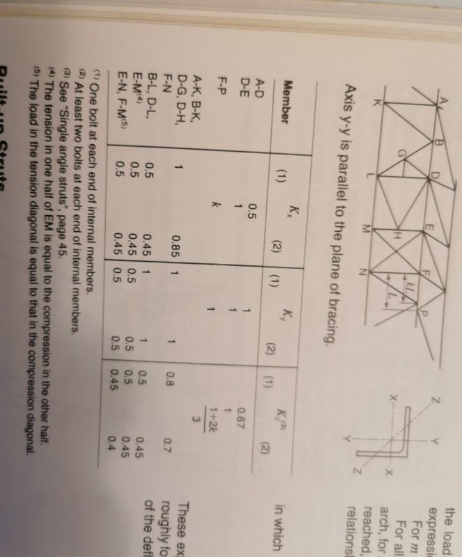
This is from a publication by Alcan titled "Strength of Aluminum" I had the entire publication scanned, but cannot find it. You may have to tilt your monitor 90 degrees... The publication is from 40 years back.![[pipe] [pipe] [pipe]](/data/assets/smilies/pipe.gif)

Rather than think climate change and the corona virus as science, think of it as the wrath of God. Do you feel any better?
-Dik
![[pipe] [pipe] [pipe]](/data/assets/smilies/pipe.gif)

Rather than think climate change and the corona virus as science, think of it as the wrath of God. Do you feel any better?
-Dik
- Thread starter
- #10
Thanks, this is a really good start.
If you look at the middle line for A-K, B-K, D-G, D-H and F-N, it allows a reduction for Kx and Kz.
I'm guessing Kz applies as this is a natural behaviour (about one of the principal axis). Or was this for bending? Brace length may affect to a degree.
So for 1 bolt, Kz = 0.8 and for 2 bolts, Kz = 0.7.
Do you agree with using Kz?
-
1
- #12
Accumulated
Structural
I normally only assume them at 1.0 but see below.
Take a look at BS EN 1993-1-1 BB.1, it allows a reduction in the Lcr value.
For buckling in the plane of the truss beam: The buckling length can be taken as equal to 90% of the system length (Node to Node distance) IF the truss members are connected at each end with at least two bolts or by welding.
For buckling out of plane of the truss beam: The buckling length should be taken as equal to system length.
For buckling in the plane of the chord member: The buckling length can be taken as equal to 90% of the system length (Node to Node distance).
For buckling in the plane of the chord member: The buckling length should be taken as equal to system length.
-
1
- #13
- Thread starter
- #14
I Can't catch this.Accumulated said:For buckling [highlight #EF2929]in the plane of the chord member[/highlight]: The buckling length can be taken as equal to 90% of the system length (Node to Node distance).
For buckling [highlight #EF2929]in the plane of the chord member[/highlight]: The buckling length should be taken as equal to system length.
- Status
- Not open for further replies.
Similar threads
- Question
- Replies
- 27
- Views
- 16K
- Question
- Replies
- 1
- Views
- 2K
- Question
- Replies
- 1
- Views
- 5K
- Question
- Replies
- 4
- Views
- 15K


