Continue to Site

Eng-Tips is the largest engineering community on the Internet

Intelligent Work Forums for Engineering Professionals

  • Congratulations MintJulep on being selected by the Eng-Tips community for having the most helpful posts in the forums last week. Way to Go!

Elastic-Plastic Analysis of Vessels 3

Status
Not open for further replies.

victorpbr

Mechanical
Oct 13, 2014
74
Hi,

I`ve started some reading on Elastic-Plastic analysis, according to ASME VIII-2 Part 5. I still have a long path to go, but my first question is about which is the more suitable model of hardening to use?

On ASME PTB-3, I saw that Prager hardening is used on ABAQUS software, unfortunately I only have access to ANSYS, on Workbench, from what I saw I have basically two options of hardening models to use: Multilinear isotropic hardening and Multilinear Kinematic hardening (there are some other methods but they use different inputs than stress and strain).

From my searchs, the difference between them is basically the Bauschinger effect, but I`m not quite sure on its application.

PS: For this study of mine, I`m dealing with only with static loads.

Thanks for the attention
 
Replies continue below

Recommended for you

Isotropic hardening is what I recommend. It is best for large strains, and at the factored loads, your expectation is that the strains will be large. In general, for staid loads, it should not make a substantial difference, which is why there is no specification of a specific hardening algorithm. Note that kinematic hardening is specified for elastic-plastic fatigue, however.
 
Thank you TGS4, interesting to know that. I also read somewhere I do not remember now that isotropic hardening is not indicated for cyclic loading.

Let me address one more question, if I may. According to 5.2.4.4 step 5, if convergence is achieved the component is stable under the applied loads for that load case.Do I need to compare my stress results with any allowable? Or only convergence criteria is enough in this case?


For ex: I modelled an axisymmetric shell with 900mm radius ,pressure of 1.53 MPa and using allowable stress of 137.7, hence my minimum thickness would be around 10mm. I would expect hoop stresses of around 137.7MPa . When I performed the analysis(considering Load Case with P, only) using the factor of 2.4 (so my input pressure was 3.672MPa), my solution converged but my stresses were around 330 (which is aprox 2.4 times 137.7). However if I increase this pressure to 2MPa (with factor the input to FEA is 4.8 MPa) the solution also converges, which means it passes, however my safety factor is now less than 1.5. Am I doing something wrong?
 
Convergence is sufficient. Do not examine the stresses at the factored loads - they effectively have no meaning. If anything, check the pattern of plastic strains. (It's best to remember that while in elastic analysis, your important variable is stress, similarly in elastic-plastic analysis, your important variable is plastic strain.)

If you really want to know the true limit of your structure, run it to non-convergence, then divide the collapse pressure by 2.4.

Also, when you develop your stress-strain curve, are you going out to the true ultimate stress?
 
Geat, I was really trying to figure out some meaning from the stresses but as you said, no meaning.

Yes, I'm calculating it until the true ultimate stress, I also saw on another post on this site ( , that when implementing it into my FEA program, I should start from the proportional limit rather than the eng yield strength as the software will look for a linear behavior,and the eng yield stress will be at a nonlinear part.

In order to find the proportional limit, you said you used a value where plastic strain is near zero such as 1-e6. Which in my case means a stress of around 99MPa. Don't you think that taking the true-stress strain derivative and observing the point where the difference between two points is over a certain defined value, is a more appropriate way to do that? Or it does not really make a difference on my calcs?


Another question, this time more addressed to people familiar with ANSYS
ASME BPVC VIII-2 Annex 3-D says:
The development of the stress strain curve should be limited to a value of true ultimate tensile stress at true ultimate tensile strain. The stress strain curve beyond this point should be perfectly plastic.

Does this means, that I should input some data after the true ultimate tensile stress (basically repeating it) and increasing plastic straing? So that the perfectly plastic behavior is shown, or the simple fact that my last data is the true UTS already do that for me.


I'd like also to provide the script I'm using in MATLAB to obtain the stress-strain curve, it someone else is interested on this topic.


I've since changed my mind about the strain to define the proportional limit. My current opinion is that we should be using epsilon_p from Table 3-D.1. Nevertheless, the proportional limit stresses are indeed quite a bit lower than the engineering yield. But, the curves will be quite smooth, which will assist with convergence.

Regarding the curve being perfectly-plastic after the true ultimate stress, I'm familiar with the behaviour of both Abaqus and ANSYS, and both software assume perfectly-plastic behaviour after the final data point input. So, you don't need to do anything more.
 
Thank you, I think I got it figure out now about creating the proper material model.

I was thinking, Is it correct to say that when using this method of analysis I do not have how to assess the safety factor? I ask because, if my criteria is convergence only. If I increase my load for eg 10% my analysis still converges, hence my design would still be acceptable, but a little bit closer to the collapse point.

However since I`m factoring my loads, can I assume that this factor is 'part' of the safety factor, and works as a minimum safety factor to be used? Eg:Say my collapse load is 24MPa, if my factor is 2.4, this lead me to believe that the design would fail when under a load of 10MPa. But in reality my structure would go up to 24MPa. Hence, this 2.4 would work as a Safety Factor based on UTS, and if my applied load is less than 10MPa, my safety factor would be more than 2.4. Is this line of thinking adequate?


The load factor is your design margin (it's not a safety factor, but a design margin against a specific failure mode). That's how the LRFD approach works.
 
TGS4, What happens when the stresses in a structure reach the ultimate tensile stress? Does it not fail due to rupture? If the stresses are equal to ultimate tensile stress at some point what is the meaning of further straining of the structure at that point?
 
For load controlled loads, then reaching the UTS would indicate rupture. For strain controlled loads, stain redistribution would occur. In reality, local failure would likely govern as the failure mode.
 
TGS4, if rupture is going to happen then I think assuming perfect plastic after reaching UTS leads to non-conservative results. You see UTS is the maximum stress that a material can tolerate after that the load that it can tolerate is zero. I do not know how to exactly model this in FE software. Is it possible to consider a lower stress for strains after reaching UTS?
 
Don't forget that this is perfect plasticity in true stress-true strain plots. If you model a load-controlled load, the strain will become infinite upon reaching the true ultimate stress. Model a uniaxial test yourself, or a simple cylinder. My experience is that the FEA matches the hand calc very well.
 
TGS4, what you say is correct only if the whole section reaches that stress. Normally it is not the case. When there is a stress gradient through the thickness, there will be a region which is at a lower stress value.
 
One of the techniques that analysts use to simulate when material has reached it's plastic limit is to reduce its elastic modulus to zero. This is equivalent to element "death", in that the element no longer has any effective strength at all. What also has zero elastic modulus? Perfect plasticity.

Go through this thought experiment - thinking about loads that would otherwise (in a pseudo-elastic sense) cause primary stresses. Maybe there's a through-thickness gradient. Imagine that some of the stress reaches the true ultimate stress. Those element that achieve that level of stress at the element centroid have their elastic modulus reduced to zero (their stiffness becomes identically zero). Or you can imagine that they have been removed. The thickness is now reduced by the thickness of that element. That means that there is less material to resist the load, causing the stresses in the other elements to increase. Depending on the severity of the through-thickness stress gradient, the next element may or may not reach that same high level of stress - if it does, lather, rinse, repeat.

If you were to run a simulation of a uni-axial test specimen (putting in a tiny flaw to initiate necking at the mid-point), you will see this phenomenon. However, what is most interesting, is that the actual failure point is better predicted by a Local Failure criterion - that is that the limiting strain is a function of the state of stress triaxiality. Once necking initiates, due to the plasticity Poisson's ratio, a state of tensile triaxiality occurs sub-surface. When simulating burst tests, it has been my experience that this is often the material failure point, more so than a pure "plastic collapse" criteria. And yet the elastic-plastic plastic collapse criteria has been demonstrated to be sufficiently robust (much more than the elastic criteria) is countless experiments and tests.
 
TGS4, thank you for your explanations. I think I did not make my point clear enough. So I try again.
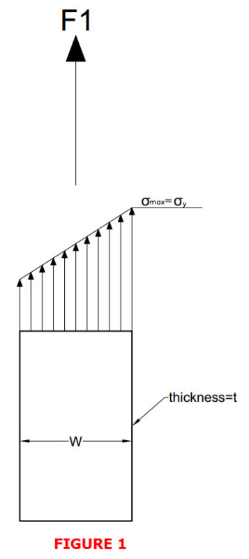
Suppose that I have a plate of width w and thickness t. This plate is a part of a component which is subject to many loads. All the loads are load controlled. The state of stress is as shown in figure 1.
Here the maximum stress occurs at the right edge of the plate. Suppose the loading has a value that this maximum stress is equal to yield stress. What happens then? Nothing happens since just on point has reached the yield and no plastic collapse will occur. Note that by integration of the stress over the area of the plate section the force acting on the section will have a value like F1.
F1_rkzrap.jpg


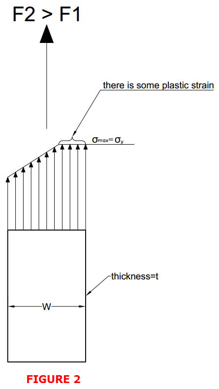
Now the loads increase and the magnitude of the force F1 increases to F2. The state of stress will change to what is shown in figure 2. Here, the points that reached the yield stress are further strained without any increase in stress value. In fact whatever the load is increased the stress does not go higher than yield no matter how much big the strain value becomes. It is the nature of an elastic-perfect plastic material model. The loading can increase further until the whole section reaches yield stress. from this point on any increase in the load is not possible since the maximum possible load for the section will be fmax = sy*t*w. An increase in the load is not tolerated and leads to unbounded deformation. I can understand that this method is conservative since in practice there will be some strain hardening and the section actually tolerates more load than what is predicted here.
F2_wbx0cb.jpg


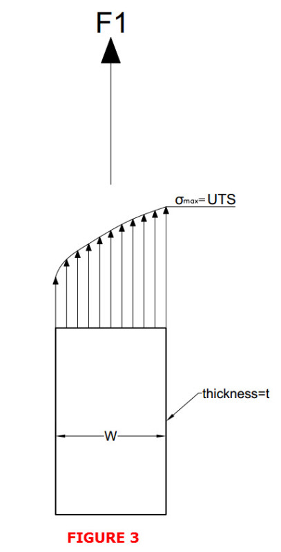
Now I want to consider the same geometry with strain hardening. After strain hardening I consider perfect plasticity. If with some loading the stress at the edge of the plate becomes the UTS then nothing happens again since there are other areas with lower stresses as shown in figure 3. Note that by integration of the stress over the area of the plate section the force acting on the section will have a value like F1.
F3_byyoxf.jpg


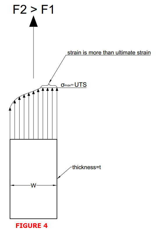
Then the loading increases and the load F1 increases to F2. The state of stress will be the same as figure 4. Here, the stresses are distributed over the section in such a way that there will be an area with stress equal to UTS. This area has a strain which is more than ultimate strain. In fact in this area first the material is subject to the UTS stress and after that further straining occurs. If the loading increases in such a way that the load F2 = UTS*t*w then any further increase in force will lead to structural instability. OK this is what the FE model says and to my eyes this is not conservative.
F4_hrhsns.jpg


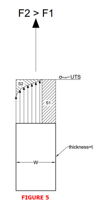
I call it non-conservative since after reaching UTS any further straining will lead to rupture at the location. Rupture means the elements will no longer carry any load. Not only it means the stiffness is zero but also the load at the location has to be zero. Setting the stiffness equal to zero is not equivalent to element death in the sense that the elements still can carry loads. Figure 5 is the real representation of the status of the plate. Since the loading is load controlled the stress distribution has to compensate for the area that has ruptured (S1). The integration of the stress has to be F2 but this time integration is taken over a smaller width not the whole width (w). In fact, if in figure 5 the area S1 is larger than S2 the whole section will fail due to rupture.
F5_yiel6s.jpg
 
Unfortunately, your analysis is a little too simplified. First thing is that you are trying to make a 1D problem into a 2D problem, but in reality everything is 3D, which starts to mess with your math and even your ability to "eye=ball" the problem.

There's a couple of things that I would like you to consider when doing these types of thought experiments. First, once you exceed the proportional limit, you will start seeing some deformation. The deformation in a state of primary bending will be towards reducing the bending. Think about a flat plate (really the only structure that exhibits primary bending) - the bending will tend to want to deform the plate into a shape that will eventually take the load in membrane tension. Internal pressure on a plate, to an excess that would reach anywhere near UTS, will result in a hemispherical head - hydroforming in other words. You will never achieve primary bending reaching UTS because of this deformation.

Second, the deformation is taking place in a 3D sense because of the Poisson's Effect, both elastic Poisson's and plastic Poisson's (which is generally regarded as a constant volume process). All of which makes the analysis much more complicated. because you need to be thinking in terms of von Mises equivalent stresses to determine when the element centroid becomes perfectly plastic, but in the context of the deformed shape (hence the need to be inputting the stress-strain curves in terms of true stress-true strain).

Third, regarding "conservatism", is the understanding that we have different design margins when we are comparing to perfect plasticity for yielding (limit load) vs strain hardening followed by perfect plasticity for ultimate (elastic-plastic).

Fourth, just as with perfect plasticity in the limit load method, all that perfect plasticity at the end of the curve is that the plastic strain values are non-physical. Which is OK for plastic collapse, because we aren't interested in the exact values of plastic strain like we are for local failure. Which is also OK, because the actual loads that the structure will see is 1/β_T of the load to cause collapse.

I hate (really hate) to say "trust me", but that fact of the matter is that the elastic-plastic method and the underlying method of LRFD work and are much more robust than the elastic or limit load methods. It may be a little bit more of a black-box approach, because the software is performing all of the load-shifting and such for you, but to me that is one of the benefits. My engineering effort is significantly reduced when I outsource my effort to the computer.
 
Status
Not open for further replies.

Part and Inventory Search

Sponsor