Eng-Tips is the largest engineering community on the Internet

Intelligent Work Forums for Engineering Professionals

Elastic Plastic Material - for FEA 2

Status
Not open for further replies.

masoodina

Mechanical
Oct 5, 2010
8
0
0
IR
hi

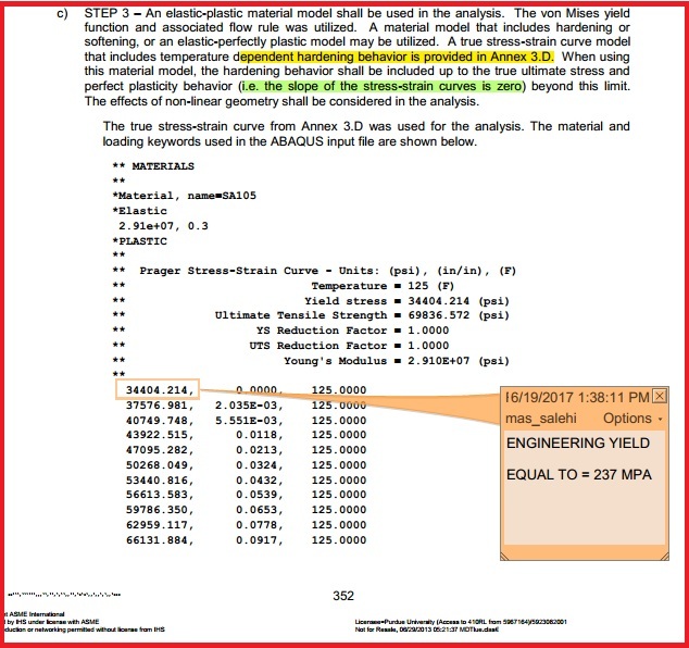
im doing an elastic plastic analysis using ansys. for the material model i used asme sec VIII div2 model.

1_egcuk4.jpg


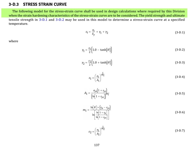
i have formulated it in excel and double checked it and it's correct.plastic strain at yield point is not zero (gamma_1+gamma_2), why ?[highlight #FCE94F][/highlight] what must i do ? in ansys i have to enter zero plastic strain at yield point.

2_ngqovy.jpg


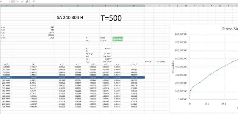
for the stresses after yield which values i have to enter in ansys material model ? just the plastic portion (gamma_1 + gamma_2)?

what is the right procedure ?

thanks in advance.
 
Replies continue below

Recommended for you

The "yield" stress listed in II-D is the engineering yield stress, which is based on the 0.2% offset method. That has the rough effect that the plastic strain at the engineering yield stress is 0.2%.

You need to start your true stress-true strain curve at the proportional limit, which will be much lower than the engineering yield, and corresponds to the stress value where the plastic strain is small - I use 1e-6.

And then when you enter the curve into your software, you input a plastic strain of zero at that point.

Clear?
 
tgs4 said:
The "yield" stress listed in II-D is the engineering yield stress, which is based on the 0.2% offset method. That has the rough effect that the plastic strain at the engineering yield stress is 0.2%.

You need to start your true stress-true strain curve at the proportional limit, which will be much lower than the engineering yield, and corresponds to the stress value where the plastic strain is small - I use 1e-6.

And then when you enter the curve into your software, you input a plastic strain of zero at that point.

Clear?


thanks. i understand your way. but two issues aren't clear to me.

1. using this method, the material will get to the plastic region sooner. wont this make errors ?
and is this method acceptable by ASME or mentioned anywhere ?​

2. [highlight #FCE94F]ASME PTB-3[/highlight] in its example, apparently has used the the engineering yield. but of course did not explain and clarify how.

1_ukwhb8.jpg


what do you think ?
 
To answer

1) Using this method, the material will get to the plastic region sooner. wont this make errors ? and is this method acceptable by ASME or mentioned anywhere:

Look at equation 3-D.11 which the yield strain is defined at 0.002 in/in. This means that yield stress is defined using the 0.2% offset. This is beyound the propotional limit, hence non-linear, with some minor plastic deformation. Some minor plastic deformation is associated with defining yield stress using proportional limit. ANSYS looks for linear-elastic response using modulus of elasticity and then non linear using Effective Plastic Strain vs. stress. This deviation begins at the proportional limit NOT yield point. Proportional limit by definition is limit of linear Hooke's law.


2) ASME PTB-3 in its example, apparently has used the the engineering yield. but of course did not explain and clarify how.


You need to look beyond terms posted in the computer output. The "yield stress" in ABACUS output is really the proportional limit. It is the point where things go non-linear. Note that plastic strain is 0.00. In your example SA-105 has yield stress of 36ksi @ 100F and 33.8 ksi @ 150F per ASME Division II. So at 125F yield is 34.9ksi. Notice that isn't what as input into ABACUS? Its slightly less, the stress at the proportional limit, where material goes non-linear.

Jeff
Pipe Stress Analysis Engineer
 
To specifically answer your questions:
masoodina said:
1. using this method, the material will get to the plastic region sooner. wont this make errors ?
and is this method acceptable by ASME or mentioned anywhere ?
Not only will this not make errors, it the technically correct thing to do. As far as being "accepted" by ASME, although it won't be in the 2017 Edition, we are working hard for the inclusion of such a clarification for the 2019 Edition. In the meantime, if you truly want clarity on the matter, please complete a "Request For Interpretation" on the ASME website as directed in the front matter in the Code. If/when you do so, please let me know.

masoodina said:
ASME PTB-3 in its example, apparently has used the the engineering yield. but of course did not explain and clarify how.
PTB-3 is incorrect and the authors have been notified.

Note that in the context of demonstrating Protection Against Plastic Collapse using the Elastic-Plastic Analysis Method, I have come to the conclusion that this is a minor concern. Typically, stresses will be much closer to the true ultimate stress (due to the factored-loads). However, there may be convergence issues as the software goes through the sharper discontinuity at the engineering yield (if you choose the engineering yield as opposed to the proportional limit).

However, in demonstrating Protection Against Local Failure using the Elastic-Plastic Analysis Method (the preferred method - see the appropriate note in PTB-1), not using the proportional limit may miss small amounts of yielding which may exceed the strain limit. At high levels of triaxiality, the strain limits can be very low - much lower than 0.2%.
 
Status
Not open for further replies.
Back
Top