Continue to Site

Eng-Tips is the largest engineering community on the Internet

Intelligent Work Forums for Engineering Professionals

  • Congratulations KootK on being selected by the Eng-Tips community for having the most helpful posts in the forums last week. Way to Go!

Electrical schematics software 1

Status
Not open for further replies.

kapmnit123

Mechanical
Nov 10, 2011
538
Dear All,
Trying to gain some insights from your experience working on an Electrical Schematics package.
We intend to buy electrical schematics software and had demos from some leading pioneers in this area.
Can you please share some recommendations regarding the same?
Some pointers : Is the software really value for money/ How comprehensive the symbol library is/ Integration ease with a PLM component (TeamCenter in our case)/how easy is to customize (adding our own symbols/templates)
Many thanks
Regards
Kapil
 
Replies continue below

Recommended for you

Hi kapmnit123
I use ProgeCAD its a once off payment no annual licence fee should you purchase it I can send you
a CAD drawing with all electrical symbols together with a typical schematic diagram.
My email paddykeys@gmail.com
 
Thanks a lot Padlock01,
We are actually looking for software which are well-integrated with Siemens Team Center.ProgeCAD do have interation with TC as well.
We are considering EPLAN/Mentor(Vesys) as of now and need some suggestions from the already using customers.
Thanks again
Kapil
 
I do not write in Eplan or CAD myself but I am a end user and have sent and received a lot of drawing changes over the years.
In my current project we have Siemens TIA integrated with EPLAN not sure what version.
So most of the information in the drawing comes from the PLC project.

Since we still uses paper drawings, there is some things that annoys me whit this drawings.
I am not sure how much of this is settings in the E.Proj and what is in the symbols themselves.

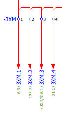
In the E.proj the drawing is A3 but when we put it on paper we use A4, this makes most of the component names and page references super small.
The E.proj is made, so it will be easy to use on a computer, so all this click and jump things are quite large, since they are to be used by the constructor.
But on paper A4 they take a lot of place while the information you need to use on a papper drawings almost cant be read.
image_xmy9qv.png


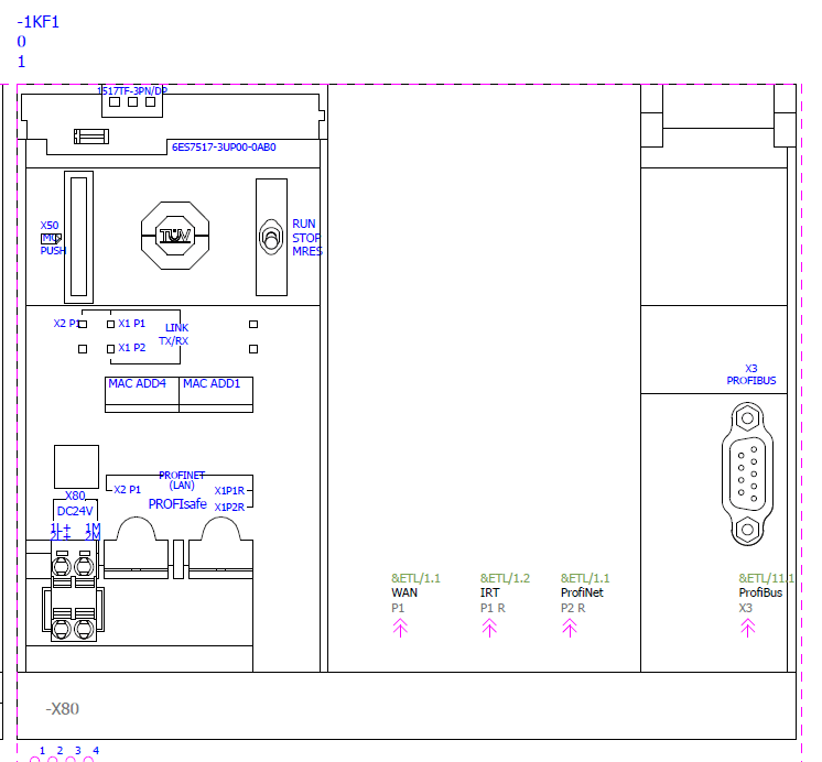
And if you can not print them in color they get unreadable, the only thing that works is printing in pure black an white without gray scale.

The same thing with some of the symbols, the information text often ends up on top of other lines and things.

image_vl0qvh.png


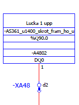
And if you use to long symbol names in the PLC they want fit the symbol unless you make the text so small you can not read it.

image_pwzmeg.png


How much of this can be fixed with correct settings from the beginning and a good struktur in the PLC I do not know.

As far as I know there is the possibility to build your own symbols, we have other drawings with none standard symbols, how smart you can make them I am not sure.

Best Regards A

“Logic will get you from A to Z; imagination will get you everywhere.“
Albert Einstein
 
EPLANE is Good for Drafting Electrical Drawing's , having library for most of the component
 
Status
Not open for further replies.

Part and Inventory Search

Sponsor