sharpie_matt
Electrical
Hi all,
I'm a bit confused about how electromagnetic clutches work. I understand there are many different designs for different purposes but I think this question applies to most designs. As far as I understand, you have an input shaft that is coupled to a rotor such that they always spin together when the shaft is driven by a motor. Then, there is a stator which contains the coils that engage the clutch when energized. The stator needs to remain stationary so it is often held in place by a pin or flange mounted to an external fixed structure and is also coupled to the input shaft with some mechanism (often ball bearings) that ensures that it doesn't spin with the input shaft. Please correct me if any of this is incorrect.
Then, there is the armature/armature hub. This is what I am confused about. I understand that you usually mount a pulley or sprocket or something onto the armature hub so that you can drive some other mechanism. But when the clutch is disengaged, do the armature and armature hub spin freely? How is the armature connected or not connected to the input shaft?
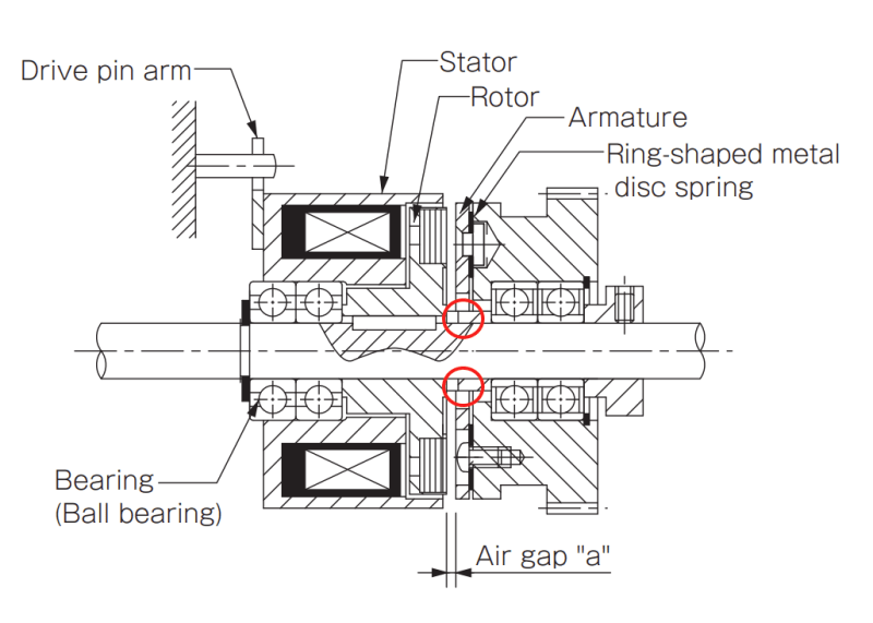
For example, in the design below, which I took from this link (Ball-bearing type mounting example with CYT), it looks like they attached a pulley (that contains its own ball bearings) to the armature hub with screws. I've circled in red what I am confused about. How does the armature hub rotate or not rotate when the clutch is disengaged?
See this thread to learn about my project. I need the armature hub to rotate freely with basically zero friction when the clutch is disengaged.
Any help is greatly appreciated.
Thanks,
Matt
I'm a bit confused about how electromagnetic clutches work. I understand there are many different designs for different purposes but I think this question applies to most designs. As far as I understand, you have an input shaft that is coupled to a rotor such that they always spin together when the shaft is driven by a motor. Then, there is a stator which contains the coils that engage the clutch when energized. The stator needs to remain stationary so it is often held in place by a pin or flange mounted to an external fixed structure and is also coupled to the input shaft with some mechanism (often ball bearings) that ensures that it doesn't spin with the input shaft. Please correct me if any of this is incorrect.
Then, there is the armature/armature hub. This is what I am confused about. I understand that you usually mount a pulley or sprocket or something onto the armature hub so that you can drive some other mechanism. But when the clutch is disengaged, do the armature and armature hub spin freely? How is the armature connected or not connected to the input shaft?
For example, in the design below, which I took from this link (Ball-bearing type mounting example with CYT), it looks like they attached a pulley (that contains its own ball bearings) to the armature hub with screws. I've circled in red what I am confused about. How does the armature hub rotate or not rotate when the clutch is disengaged?
See this thread to learn about my project. I need the armature hub to rotate freely with basically zero friction when the clutch is disengaged.
Any help is greatly appreciated.
Thanks,
Matt