Continue to Site

Eng-Tips is the largest engineering community on the Internet

Intelligent Work Forums for Engineering Professionals

  • Congratulations waross on being selected by the Eng-Tips community for having the most helpful posts in the forums last week. Way to Go!

element shape error

Status
Not open for further replies.

cirokos

Civil/Environmental
Apr 11, 2022
63
Hello everyone,

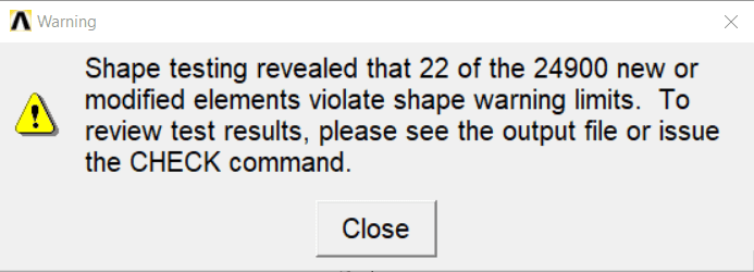
When I mesh my model this warning pops up about element shape. I tried to change the way of the mesh generation but it doesn't go away.
I want to run a non linear analysis and I think that this creates a problem for large deflection of the particular elements. How can I find a way to overcome this ?
%CE%A3%CF%84%CE%B9%CE%B3%CE%BC%CE%B9%CF%8C%CF%84%CF%85%CF%80%CE%BF_%CE%BF%CE%B8%CF%8C%CE%BD%CE%B7%CF%82_2022-08-29_203331_ezkxzf.png
 
Replies continue below

Recommended for you

I would also be very interested to know the information on this subject ..
 
Perhaps indicate what software your using, what kind of model, what kind of elements, mesh settings, boundary conditions ???
 
What follows is a general statement and may not be applicable to your somewhat vaguely defined query.

An element shape ERROR suggests to me that you have listed the element's defining nodes in the wrong order.[ ] As an example, consider a four-noded quadrilateral element that is a unit square.[ ] Some FE programs require you to define the element topology clockwise, ie [(0,0) (0,1) (1,1) (1,0)], while others might require a zig-zag presentation [(0,0) (1,0) (0,1) (1,1)].[ ] If you get this wrong the program sees it as a geometric impossibility, hence it knows you have made an error.[ ] Alternatively, in a three-dimensional model you might be required to have all two-dimensional elements planar, and the error message might be telling you that you have not met this requirement.

An element shape WARNING would probably be something different.[ ] As an example, four-noded planar elements are at their most accurate if they are square.[ ] The further they deviate from squareness the greater the mathematical inaccuracies.[ ] An element [(0,0) (0,1) (1,0.1) (1,0)] might result in a warning because the software developers feel it is too distorted from the ideal shape.
 
Hello everyone,

The subject is an analysis of an aluminum honeycomb core. I am trying to run a non linear analysis of the model to see the buckling initiation in the cell walls.
The program that I am using is Ansys mechanical apdl. For the analysis, only shell181 elements are used and a general element size of 0.5 ( for the meshing). Boundary conditions trying to simulate those of a shear test from ASTM standard. If you like, I could explain how I implement them in the FE program.

Denial,
That's a very interesting explanation and needs further explanation. I found out that when esize is 0.5 no such warning occurs. On the contrary, when I turn on non-linear geometry ( NLGEOM, ON) the model collapses with an error message that one element has exceeded distortion which I cannot explain. Any thoughts on that?
 
Firstly I have never used Ansys, secondly I have no idea what "esize" is (and am not asking), and thirdly my comments were deliberately very general.[ ] I can[ ]not / should[ ]not offer anything further.[ ] However I am slightly puzzled that you get this warning when you attempt a geometrically nonlinear analysis but not otherwise.[ ] Maybe Ansys does its shape checks on the current distorted shape of the elements and your troublesome element(s) are close to the threshold, or maybe your analysis involves extremely distorted deflections.
 
Status
Not open for further replies.

Part and Inventory Search

Sponsor