Eng-Tips is the largest engineering community on the Internet

Intelligent Work Forums for Engineering Professionals

End-cap pressure thrust in piping stress calculation

Status
Not open for further replies.

NPengineer

Nuclear
Aug 14, 2022
4
0
0
GB
Hello all,

Having recently started doing pipe stress calculations, I have been trying to test my understanding against some simple computer models using PIPESTRESS software.

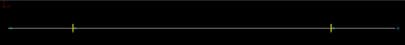
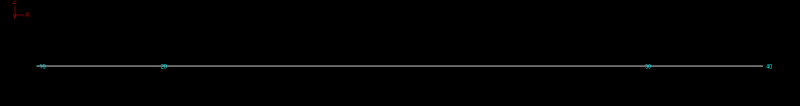
I have modelled a horizontal length of pipe, with two anchors, and some pipe overhanging the anchors, as shown below:

Pipe_with_anchor_pa1fdf.png


I have applied no temperature (I am aware that the thermal loads between the two anchors would be huge), but have applied a uniform pressure load. My thinking was that:
1. The pressure would result in end-pressure loads (P*A_int) on the end-caps, which would be reacted by horizontal loads
on the at the two anchors, directed towards the centre of the pipe. I also think there would be another horizonatal
force on the supports acting in the opposite direction, (due to the center length of pipe wanting to contract due to
poisson effect), but these shouldn't cancel out exactly.
However, in the computer analysis I ran (using Editpipe software), there were no horizontal loads at all on the
anchors.
2. Furthermore, the longitudinal stress on the pipe was came out as uniform throughout the pipe, even though I would
expect the stress in the two end-sections to be (P*D)/4t, and the in the middle section to be slightly lower
(poisson's ratio)*(P*D)/(2t).

I am probably missing something simple here, if so please correct my reasoning. If not, is there a reason why these end-cap pressure loads are not included in piping software analysis? I can't imagine it is a rare situation that they would react directly at supports, and surely the support designers need to know these loads?

Many Thanks
 
Replies continue below

Recommended for you

That drawing is very difficult to see.

Are you sure the anchors are modeled as rigid 6 way anchors and not supports?

Is there any movement?

Does the model start at P=0 then you apply pressure?

Remember - More details = better answers
Also: If you get a response it's polite to respond to it.
 
Apologies, hopefully the image below is a little bit clearer.

pipe_with_anchor_2_kakgvc.png


The anchors are definitely rigidly restraining all 6 movements. There is no movement at all except for downward displacement due to self-weight.

Not fully sure what you mean by the pressure starting at 0? I defined the geometry and then set up a loadcase where the pressure was to 10 MPa.
 
MJC, He's using PIPESTRESS, which looks like a specialist nuclear piping thing..


It may be your just not asking the sitar the right question. What code are you using and what size pipe etc. Are the anchors showing vertical forces?

Maybe try one anchor and one sliding support and see if it moves?

Remember - More details = better answers
Also: If you get a response it's polite to respond to it.
 
The unit file should list a start status, ( temp, pressure, etc) and then the changes to a higher pressure or temperature or other load like wind.

Remember - More details = better answers
Also: If you get a response it's polite to respond to it.
 
Bourdon effect option can be used if the software has it. Generally this internal pressure axial effect is contained by the pipe wall itself depending on pressure, wall thickness and diameter. If excessive, it will obviously load the supports.
 
Code is RCC-M (French nuclear Piping Code) and the pipe for this test case is DN50.
The reference pressure is 0 yes and then the pressure in the loadcase in question is 10 MPa, with no rise in temperature.

From reading around a bit I think I have tracked down the problem to be the way the computer code implements the end-pressure thrust.

I have no run two analyses, one (originally) with the bourdon effects(in this software called pressure elongation) turned off, and one with it turned on. However, I don't think either of these cases reflects the reality of the situation.

With the bourdon effects turned off, there is no horizontal reaction force on the two anchors when there should be a net outward force (away from the centre) on them.
With the bourdon effect on, it seems to just try and apply a uniform strain to the piping, much like a thermal strain. This means that essentially the restrained section between the two anchors tries to expand, and it cannot, leading to net outward reactions on the supports. This does give a force in the right direction, but not not of the same magnitude as it should be in reality.

It seems like the only correct way of modelling it would be to apply:
1. a force loading at every end-cap (and closed valve/elbow etc) and,
2. a uniform strain equal to the Poisson effect (of hoop stress)

But from what I have seen, nobody seems to model it that way? Fair enough it seems like doing it the normal way does conservatively cover the longitudinal stress in the pipe, but not the loads on supports...
 
Why do you think that does not provide the correct support loads?

End cap pressure loads would be transferred completely to interior supports.
Poisson stresses in the free end are not restrained, therefore result in no axial load to the supports.
Poisson stresses within the restrained segment are of course restrained, thereby resulting in loads to the supports.
Support loads would seem to be the algebraic sum of the loads.

Are the supports full 100% anchors? If movement is allowed, forces will reduce.

Your description seems to be the same as mine, yet you say that the resulting Bourdon incluseve loads are incorrect.

I think we need to investigate how the code implements the algorithm. Assuming that you cannot see that math, we first need to determine the amount of the error and postulate why it exists and confirm why it shouldn't, if that is the case. This should be easy, as you have no thermal component.

It seems that the Bourdon effect being on includes Poisson and the end cap pressure loads. Off, does not include them. What support loads do you get when on? Off?

What's your data and calculation look like so far?

Einstein gave the same test to students every year. When asked why he would do something like that, "Because the answers had changed."
 
Thanks, for all your help folks.

@1503-44, yes I have rechecked my work and come to the conclusion that we were indeed saying the same thing, and furthermore that the software (with the bourdon effects turned on) does give the correct loads on the supports.

If we consider the loads on the support on the left, it has two forces acting on it, F1 (due to endcap pressure thrust) pulling it to the left and F2 (due to possion effect of the restrained section of pipe), pulling it to the right.

Essentially, F1 = P*A_int
F2 = -v*(PD/2t)
And F_tot = F1 + F2

While the software just implements an uniform strain, which results on a force pushing the support to the left:
F_tot = (1-2v)(PD/4t)*A_wall

It took me a little bit to convince myself that these were actually the same forces, but I now see that they are. However, doesn't it still mean the stress in the central section is incorrect? The software has it in compression, but i believe it should be in tension?
 
It should be tension.

What software are you using?
Stress conventions are sometimes are reversed. I think it's the RISA structural analysis program that uses conventions completely backwards from what I learned. That's crazy. I can't use that one. Check the manual.

Pipe next to the caps are in tension, right?
Both supports totally rigid, right?
No slide plates, right?
And the number is correct, but the sign is reversed?

These is probably the best detailed explanation I've seen in quite awhile, if you can get past being confused by effective and real end nozzle loads. Seems like he also answers at least some questions there too.


Einstein gave the same test to students every year. When asked why he would do something like that, "Because the answers had changed."
 
Status
Not open for further replies.
Back
Top