Eng-Tips is the largest engineering community on the Internet

Intelligent Work Forums for Engineering Professionals

  • Congratulations waross on being selected by the Tek-Tips community for having the most helpful posts in the forums last week. Way to Go!

EPANET: Problem Negative Pressure 1

Status
Not open for further replies.

Vecchi_Giacomo

Civil/Environmental
Mar 27, 2019
1
0
0
RW
Hello Everybody!

I'm working on an EPANET project, it's a gravity system for irrigation.
I have some problem 'cause I have only 1 tank at the beginning of the network and during the simulation it is empty.

error_ysku9b.jpg


I was create 2 patterns cause I will irrigate in the morning or in the evening, it's impossibile irrigate during the day; sun will burn everything.
I have, also, another problem: I will use pipe PN10, so i must install some Break Pressure Tanks, so I create some Tanks to reduce the pressure, it's correct or it's better insert a PRV Valve?

I will Attach my project

Thanks you
Giacomo
 
Replies continue below

Recommended for you

Since this is an irrigation system that is either on or off, I would use emitters instead of a base demand
that would do the proper simulation, then look at the flow from each emitter and adjust the diameter of the orifice to get the right spray pattern.
As for the in distribution tanks, if they are not there in the system do not put them in the model.
Use the PRV valve (or a general purpose valve if the actual valve is direct acting) as a Model PRV is acting like a Pilot operated PRV.
To use the General purpose valve you will have to create a flow vs down stream pressure look up table.

Hydrae
 
I have not used EPANET for several years and am having problems with negative pressures in my system. The system is a water distribution for a apartment complex which ties to existing water system. Does the reservoir need a pump to overcome the negative pressure?

Also the pipe in one of the loops seems to be reversed.

Any suggestions?

Ellie M
 
 https://files.engineering.com/getfile.aspx?folder=e7d2a826-76b4-4117-8a47-1b7e2d672694&file=Water_Modeling_RES.net
Ellie60…

Many of the node demands are impossibly high (e.g. Nodes 7, 12, and 16 each have a base demand of 240,000 gpm!). This obviously leads to impossibly high flow velocities and head losses in pipes that are only 6" or 8" in diameter.

Also, Reservoirs 32, 33, and 34 are at approximately the same elevations as the nearby nodes, which means they are too low. Reservoir 22 seems to have an appropriate elevation.

When I changed the heads of the three offending reservoirs to 5,000 ft (arbitrary) and all non-zero base demands to something less than 100 gpm, the model ran successfully.

I hope this helps.

Fred

==========
"Is it the only lesson of history that mankind is unteachable?"
--Winston S. Churchill
 
Ellie60…

I had a few more minutes to look at your model and I have a couple suggestions:

Pipes 2, 5, 6, 7, 10, 11, 15, 16, and 27 are all 10 feet long or shorter. Do you need each one of these short pipes (or even the few that are a bit longer), or can you combine them with adjoining pipes? It might require shifting a demand a few feet to a "combined" node, but that's usually OK. On the other hand, sometimes nodes that create short pipes are needed for some future extension of the system. Regardless, you know your system best and only you can determine the best way to define it.

I suggest renumbering the nodes and pipes to make the model easier to work with. Since there are two separate systems (which is fine) and both are stick systems, I suggest calling the bigger one the "A" system and the smaller one the "B" system. Then, I suggest numbering pipes and nodes sequentially from one end to the other for both systems. In addition, some modelers like to prefix nodes and pipes with "N-" and "P-", respectively, which makes the map of the piping system easier to understand. So, starting from the top of the "A" System, you might have for reservoirs and nodes, R-A01, N-A02, N-A03, N-A04, and so one and for pipes P-A01 from R-A01 to N-A02, followed by P-A02 from N-A02 to N-A03, P-A03 from N-A03 to N-A04, and so one. The "B" system would be handled the same way, with the additional choice of duplicating the numbers and letting the letters distinguish the system (e.g. N-A02 vs N-B02) or using new numbers with a gap between the two systems (e.g. N-A02 vs N-B52). Either is OK, but here I would choose the latter as a fail safe. Finally, for systems subject to future expansion (not likely in a building), we usually use a "gap numbering" scheme, such as N-005, N-010, N-015, etc. or even N-010, N-020, N-030, etc.

Fred

==========
"Is it the only lesson of history that mankind is unteachable?"
--Winston S. Churchill
 
Ellie60…

I found the following problems:
-- In the new model you posted, Pattern 1 (which determines how the base demands are factored up or down for each time slice) shows a multiplier of zero across the board. This makes all node demands zero and we are left with flows running straight from the two higher reservoirs (22 in the bigger system and 32 in the smaller system) to the two lower reservoirs (34 and 33, respectively). On the other hand, this condition produced velocities ranging from about 3.3 fps to about 6.4 fps, which is reasonable even if it's a fictitious situation. [smile]
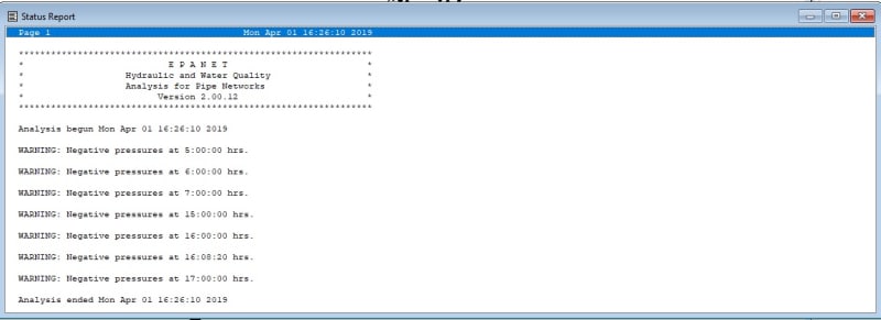
-- When I edited Pattern 1 to use a multiplier of 1.0 for the first time slice, I landed back at the same problem you mentioned: extreme velocities and negative pressures.

Fortunately, you renamed the nodes (not as I suggested, but your method is OK too), so I was able to figure out what the real problem is. Well, two problems, actually.
-- All fire hydrants are flowing at the same time, which is unrealistic. The standard of practice is to run one fire flow at a time.
-- Four of the building demands are still far too large for the pipe sizes you are using and probably too large for the buildings themselves: 4,125 gpm at Bldg A-F, Bldg B-F, and Bldg C-F and 2,625 gpm at Storage F. I suspect errors in the method used to estimate building demands.

Solutions:
-- Consider which demand levels you need to run. For most systems, the critical high flow scenarios are [1] Peak Hour Demand (PHD) and [2] Maximum Day Demand Plus Fire Flow (MDD+FF). For some municipal systems, a minimum winter-time flow scenario is also required to deal with water quality issues stemming from low flow conditions. Some systems can have other specific requirements. When I set up a model for situations like yours, I use the Average Day Demand (ADD) for my base demand. Then, assuming I am not running a true time period simulation, I usually set the demand factor for the first time slice to 1.0 (ADD/ADD =1.0), the second demand factor equal to PHD/ADD (in my experience, this is usually in the 3.0-4.0 range, but it can be smaller, larger, or much larger). All remaining time slices I reserve for however many MDD+FF scenarios I need to run (see following bullet).
-- If your fire flow requirement is 1500 gpm, you may want to split it so that 1000 gpm is at one hydrant and the remaining 500 gpm is at the next nearest hydrant. This is a common procedure that I have discussed several times over the years here. You may find these discussions useful: and and Here is some additional guidance I provided a few years abo about EPANET that includes more information about fire flows: It's a LONG thread, but there are a lot of good nuggets in there. If you want to test fire flows at multiple locations, then it's simply a matter of using multiple demand patterns to adjust flows between zero and your base fire flow (or, for the split I suggest, then using factors of 0.66 and 0.33 against a base fire flow demand of 1,500 gpm). In this case, you are running a time period simulation, but where time is irrelevant. The time slices are there to separate different fire flow locations.
-- You may want to evaluate building peak demands using the Fixture Unit Method, if your plumbing code uses it. Here are two discussions about it: and Eng-Tips has a couple dozen threads about the Fixture Unit Method.

I hope this helps. If you need more guidance, just let me know.

Fred

==========
"Is it the only lesson of history that mankind is unteachable?"
--Winston S. Churchill
 
Fred
The high flows at the buildings are for the sprinkler systems which I calculated using IFC. Each of the nodes are fire lines to the buildings.

The model I posed was for the Peak Demand, I created different models for ADD amd MDD not sure if this is correct way. I assume I could use time patterns for the different scenarios.

I will read the additional threads.

Thank you for all the help.
Ellie
 
Ellie60…

Ah, sprinklers! Well, again, you should only model one fire at a time. I suggest checking with your local agency (probably the fire department) to see how they want you to handle the combination of hydrant flows and sprinkler flows. Long ago, one agency had me check things like [full hydrant flow plus partial sprinkler flow] vs [partial hydrant flow plus full sprinkler flow]. But, when in doubt, I run one full external fire flow (using one to three hydrants depending on the required flow--see the threads I reference above for details) PLUS one full internal fire flow (sprinklers) PLUS the Maximum Day Demand for the system, including the building we just lit on fire. That's the worst case that we are generally obligated to check.

That being said, one 1,500 gpm hydrant flow plus one 4,125 gpm sprinkler flow (5,625 gpm total) is too large for 8" pipes. If we could split the flow exactly in two (2,812 gpm), so that half comes each reservoir, we would have a flow velocity of nearly 18 fps. This is too high. During an emergency, I am reluctant to exceed 10-12 fps in mains and 15 fps in hydrant laterals. BUT, if the fire is closer to one end of the system or the other, then the flow in the shorter side will be higher and the flow in the longer side will be lower (this is to balance head losses). In an extreme case, maybe 90% of the flow would come from the closer reservoir, with 10% coming from the more distant reservoir. This means that you could have perhaps 5,062 gpm max in the short side pipes. For an 8" pipe, this is a whopping 32 fps. In fact, you would need a 14" pipe to get the velocity down to an acceptable 10.6 fps.

========================

BTW, these required flows have safety factors built in to them that are owned by the fire department. That way, if the fire jumps to second structure there should still be sufficient system capacity to deal with it (hopefully). We can't touch that safety factor, but it's good to know it's already included and we don't need to add our own on top of it.

Years ago I had a friend who worked for the Ventura County (California) Fire Department. He told me that the code requirements for fire hydrant flows were generally about 1.5x to 2.0x (or more) what was actually required to fight a single-structure fire. (There are a lot of variables in fire fighting, so safety factors are fuzzier than the ones we use for structural design.) So, for houses that required a 1,500 gpm fire flow by code, it would take maybe 600 to 1000 gpm to actually fight that house fire.

I have first-hand experience with this. In 1986, the house next door caught on fire in the middle of the night. An electrical short in the roof-mounted air conditioner caught their 15-year-old cedar shake roof on fire. Our neighborhood had a fire flow requirement of 1,250 gpm per the code it was built under. The fire department used two hoses from two hydrants, each probably producing around 300 to 400 gpm (typical fire hose flows are in the 300-800 gpm range depending on system pressure; our system ran at the lower end of the normal pressure range). Add to this another 10-15 gpm or so that one of our neighbors (a fire fighter with another agency) applied to our roof using one of our garden hoses to minimize the damage to our roof.

Fortunately, nobody was injured. Our neighbor's house was a total loss, but was quickly rebuilt, and our house had about $4,000 worth of damage (about 1,000 sf of cedar shake, two broken windows from the heat, melted mini blinds, etc). Oh, and I had to throw our insurance adjuster off our property after the misogynist insulted my wife and then me. I immediately told our broker to have the insurance company send out a new adjuster and then find us a new insurance company. I'm not still angry about this. :)

==========
"Is it the only lesson of history that mankind is unteachable?"
--Winston S. Churchill
 
Fred
That is terrible the house started on fire. My sister's house caught fire and did a lot of damage they were able to save the house. We are building a home in the mountain west of Denver and we are required to install a sprinkler system it is mandatory in the county next year. Cost us a fortune. [mad]


I have to submit to the jurisdiction but will keep working on the model.

Do you have any You-Tube or webinars that you teach for EPAnet? I would like to see how to set up the Time patterns for the Max and Peak demand and also how to adjust the models for fire flows.

I do appreciate all the help since I have not ran EPAnet for awhile and with all these flows.

Ellie
 
Ellie60....

The only things I have posted on YT (and it was a while ago) were some timelapse photography projects I did. Search for skysurfer5cva. If you look at the comments on a few of the videos, you will see me responding to a nutcase who is no longer on YT, hence his posts disappeared and you only see my responses.

I will check my electronic archives to see what I have handy that is relevant to your project. Even though it doesn't apply to your case, you may find this thread useful: (there I attached a file for simple pumping station design and it shows how I use the time period simulation feature to generate system curves).

Fred


==========
"Is it the only lesson of history that mankind is unteachable?"
--Winston S. Churchill
 
Ellie60....

Here are two OLD examples from my electronic archives that use the Time Period Simulation feature to move fire flows around. How old? EPANET 1.0 old. I may have newer examples somewhere, but they're not on the thumb drive I have at the office. Also, these two models are not quite set up as I suggested, but at least the fire flows are. I have included the original EPANET 1.0 input files (.inp), new EPANET 2.0 network files based on the old input and map files, and new EPANET 2.0 input files that I exported from the new network files. It's easier to read the PATTERNS in the EPANET 1.0 input files, but the EPANET 2.0 input files are current and don't require separate map files.

Here are the models:
-- P1996BRF.net - This model covers the City of Clovis, CA, water distribution system (as of 1996) plus two proposed residential developments. This was a hand-me-down model. Some other consultant prepared the original version of the water model (which may or may not have been in EPANET) in about 1990. One of the engineers at the City then took it over and kept it updated (mostly). In early 1995, one of my co-workers got the model from the City to model one of the proposed developments. He didn't do it right: he modeled a single fire flow at the entrance to the development and called it good. Then, in late 1995, he asked me to model a second proposed development on an adjacent parcel because he didn't have time. I soon discovered various problems with the underlying network, including some typo'd pipe diameters, a couple incorrect well capacities, etc. After fixing the obvious errors, I added the first development's internal water system and modeled a fire flow at the far end. You guessed it, the pressures were too low. This was mostly caused by my co-worker undersizing a long proposed main (maybe a mile?) from the existing system to the new development. Fortunately, the addition of the second development allowed me to salvage the situation without embarrassing my coworker. The second development required upsizing the connecting main from both what he had and from what I determined it should have been for the one development. So, no harm, no foul. Anyway, the model tests fire flows at nine locations. For this model, I set the base demand for the fire flow node to be the required fire flow and used peaking factors of zero and one to turn the fire flows off and on.
-- Vv-FFPS.net - This model covers a correctional institution (actually two adjoining facilities on the same property). It dates from 1999. I built this model from scratch, then turned it over to another consultant (whom I already knew) when he had to add a third facility to the property. For this model, I set the base demand at the fire flow nodes to 1.0 and used peaking factors that matched that portion of the fire flow assigned to that node plus the MDD flows at the same node. Either way works, but logically it makes more sense to use actual base demands and peaking factors of zero and one. I suspect I used this "alternative" method here "just because I could." [smile] The good thing is, this shows you the two methods I talked about in one of the threads I referenced above.

I hope this helps.

Fred

==========
"Is it the only lesson of history that mankind is unteachable?"
--Winston S. Churchill
 
 https://files.engineering.com/getfile.aspx?folder=561c7c51-b5fb-4ccf-bfee-f56c6a6de8c6&file=EPANET_Examples.zip
Status
Not open for further replies.
Back
Top