Eng-Tips is the largest engineering community on the Internet

Intelligent Work Forums for Engineering Professionals

Equivalent Frame Method- Column Axial Load

Status
Not open for further replies.

hoshang

Civil/Environmental
Jul 18, 2012
479
0
0
IQ
Hi all,
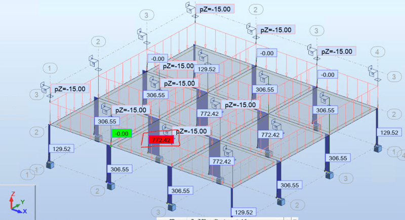
I tried to find out column axial load for Example 13.3 in Nilson's Design of Concrete Structures textbook, SI units, 14th so I can compare it with Autodesk Robot Structural Analysis.
Please find attached link:
Column_axial_load_xeon35.jpg

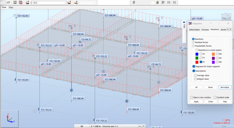
Robot results 335.71kN
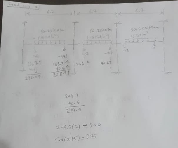
My hand calculation results: 375kN
Is it comparable? Is my hand calculation correct?
 
Replies continue below

Recommended for you

Is your Robot model a 2D frame also or full 3D plate model?

I am also not able to follow your hand calculation recommend you plot the shear diagram for the frame.
 
Celt83 said:
Is your Robot model a 2D frame also or full 3D plate model?
3D plate model
Celt83 said:
I am also not able to follow your hand calculation
Sorry, my mistake.
Please find the attached link:

I think it's comparable with Robot results.
 
 https://files.engineering.com/getfile.aspx?folder=7ab20ae0-3504-48ea-93f3-7670e73100b2&file=Column_axial_load.jpg
I believe your updated calculation is the shear in the slab if so the column reaction would be the difference in shear between two bays which based on the numbers you show would be around 713+/- Kn.

Are you sure you are comparing the same applied loading between the two analysis.

Also note that the Equivalent Frame Method is a 2D frame model of the 3D structure so there is an overlapping load region, typically you would do tributary area for the column axial load. Assuming this is a regular grid then by tributary area you would get around 6.7m * 6.7m * 15 Kn/m^2 = 673.35 Kn, based on this your loading or support conditions in Robot may not be correct.
 
In your robot model make sure the support condition for the columns above the slab allows for vertical movement otherwise they will act as hanging supports.
 
The image reference your posted from SPSlab is for a single span your interior column is supporting two spans you must add the the shear from the two spans to get the total reaction at the support this follows from statics/ mechanics of materials.

In your Robot model is it indicating Fx force in the column above the slab?
 
Celt83 said:
The image reference your posted from SPSlab is for a single span
No. It's for 3 bay span. Look at problem statement:
3_bay_hhftol.png

Celt83 said:
In your Robot model is it indicating Fx force in the column above the slab?
No. In my Robot model it is indicating Fx force in the column below the slab.
By the way, are you DonBAE in Autodesk Robot Structural Analysis forum. He was helpful.
 
Here is the results with 15 Kn/m^2 over the whole slab with the top supports corrected from the model you posted in the Robot Forums:
Interior Column Axial load = 772.42 Kn, this is larger than the tributary area results due to 3-Dimensional continuity and axial shortening of the columns (EFM of the example problem does not account for axial shortening)

Screenshot_2023-09-23_162823_wzsik0.png
 
I revised your top supports to release Uz, made a new live load case LL4 and applied a uniform 15 Kpa surface load to all panels. Ran the model then Results > Diagrams for bars > Fx (make sure the correct load case is active)
 
Releases on the members are defined locally support conditions are defined on the global axis.
Screenshot_2023-09-23_173638_okt3bf.png


See also this quick static proof of the interior reaction of the 2D frame model:
Screenshot_2023-09-23_173316_etra39.png
 
Celt83 said:
made a new live load case LL4 and applied a uniform 15 Kpa surface load to all panels.
Instead I have separate dead and live load cases and combinations. I get 336.10kN rather than 772.42kN for case component 4. Can you have a look at my model? Or attach your model in eng-tips or Robot Forum?
Even if I make a new live load case LL4 and apply a uniform 15kPa surface load to all panels, I get 386.94kN rather than 772.42kN.
 
Not around my computer today but can check later, what load component are you looking at results for in your model? It is very likely the load condition you are looking at in Robot is not consistent with the EFM example problem.
 
“ Even if I make a new live load case LL4 and apply a uniform 15kPa surface load to all panels, I get 386.94kN rather than 772.42kN.”

Then you have not corrected the top node support conditions, you need to allow UZ translation at the top nodes. Instead of looking at bar diagrams just simply look at Fz reactions.

Post a screen shot of both the bar Fx diagrams and a screen shot of the Fz reactions and make sure you do not have the story filter turned on so it shows results for all the members and supports.
 
hoshang said:
Even if I make a new dead load case DL2 and apply a uniform 15kPa surface load to all panels, I get 386.94kN rather than 772.42kN.
Please have a look at this screancast:
Reactions_ow46nx.png

As you can see, I released UZ of the supports, applied 15kN/m^2 on all panels for DL2, ran and get 386.94kN FZ reaction.
 
All of your top nodes have Fz reactions you have not applied the correct boundary condition the top nodes must allow global Uz translation.
 
Status
Not open for further replies.
Back
Top