Since no one comes forward I put a few pointers of a retired guy to see if we could ignite the discussion.
I haven't done this type of design for years as the junior engineers would take care of it. My contribution is only on the ways to go about it and the methods of analysis.
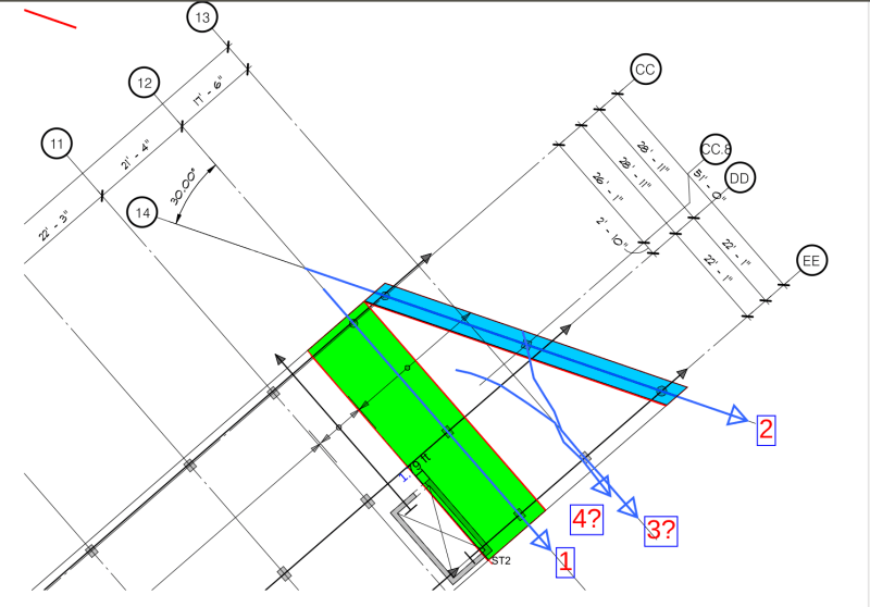
Since frame analysis is mentioned but the design is a 2D slab so I assume first there are structural beams along Gridline CC,DD and EE in order the slab is analysed as a 1D beam, like the area hatched in Green or marked as [1]. This is the standard unit width concept with which a 2-bay continuous beam, say with 1m width, is analysed and designed. If the design is adequate for 1m width then by joining 1m strips together the design is expected structurally adequate too for the whole slab because the strips are in fact cast monolithically and has secondary reinforcement, as per design code, orthogonal to the two-bay beam direction.
The same concept can be applied to the irregular section with the worst span along Gridline 14 which is expected to have rebar area more than the span along gridline 12. This method breaks down when the main reinforcement, in the two-bay beam direction become too congested at the support on Gridline CC where the bar spacing is reduced to about 1/4 (by inspection) of the opposite side (Gridline EE).
As a designer one can introduce, say subject to the approval by the architect, additional beams along Gridline 12 and 14 so that the stab can be structurally supported along the shorter span in each bay. That is likely to meet with some resistance.
The slab can always be designed as a 2D plate with the columns in their exact positions with or without the structural beams. This will give the moments Mxx, Myy and Mxy with which the reinforcement can be designed. I personally expect this route to be followed as nowadays such analysis is routine in a design office. One can perform a 3D finite element analysis with it but the simpler 2D thin plate theory is acceptable world wide AFAIK.
The application of beam analysis to a slab is fine but if a slab is skew and irregular there will be wrapping moment which the beam theory does not cover. If you cannot mitigate this risk the that will be the time to switch to plate analysis, unless one has the benefit of secondary beams to justify the simplification the way I described above. Beam theory design in a slab still needs reinforcement in the other or secondary direction in every code and this must be followed. The presence of the rebar in the secondary direction permits the design based on beam theory as the beam in this case has any shear links. Punching shear will have to be looked at in each column though.