Continue to Site

Eng-Tips is the largest engineering community on the Internet

Intelligent Work Forums for Engineering Professionals

  • Congratulations SSS148 on being selected by the Eng-Tips community for having the most helpful posts in the forums last week. Way to Go!

equivalent spring constant of one support in a support system 1

Status
Not open for further replies.

Rich2020

Civil/Environmental
Apr 12, 2022
5
Hello folks,
Currently I got a task to obtain the equivalent lateral stiffness of one support in a steel skid supporting piping system. These are 25 supports on the structure at different elevations - some are T-post and some are frames. The common steel skid is supported on 10 piles. It has been modelled in Staad. The question is how to get the equivalent spring constant at each support location.
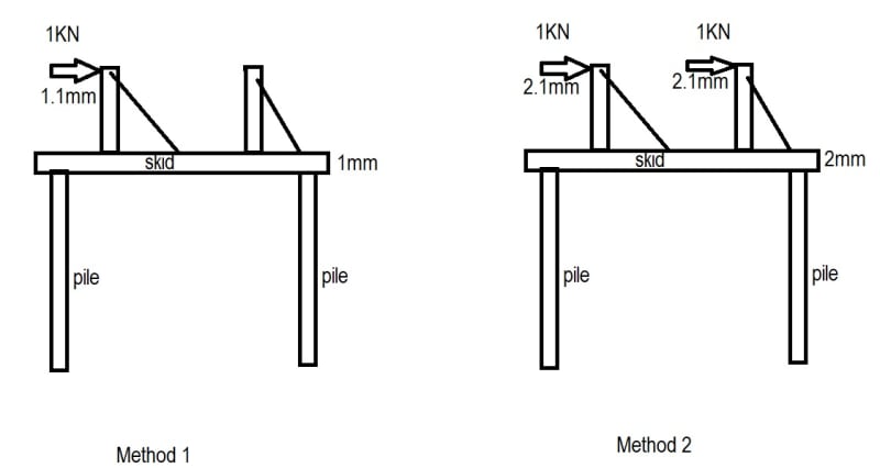
My initial thought was to add a force on one support only and obtain the lateral displacement Δ from Staad then the K = F/Δ. this equivalent spring constant should have considered the stiffness of pile/soil, skid and the support.
Then I got questioned that how the other supports will affect this support's stiffness since all the supports are loaded on a common skid supported on same 10 piles. The argument was that the equivalent stiffness of one support should be the force on this support divided by the support lateral displacement with the loads applied on all the supports in Staad. If this concept is correct, then the equivalent stiffness of one support will not be a constant and be function of the loads and stiffness of other supports.
I'm confused with the argument. Can anyone help? TIA!
 
Replies continue below

Recommended for you

Your method is correct, however, you need to connect the supports to form a system, then apply unit load on each one of them and obtain k11, k12, k21....and so on. It's been a long time since I did that, so I could,t take you to walk through the problem step by step, but if you are familiar with the matrix method, it will make sense to you. A quick review on using the matrix method solving system problem will help.
 
Thank you @le99 for the reply. I'm wondering which method is correct in theory. The system has been modelled in Staad. The first method is to apply only one load on one support to calculate the support's stiffness. The second method is to apply all loads on all supports to calculate the support's stiffness.
Based on the first method, the support stiffness is a constant.
Based on the second method, the support stiffness is variable of magnitudes and quantities of the loads and supports.
 
IMO, for lateral stiffness concerns, either method could be valid, since we can assume the lateral load is uniformly distributed to each support. You can try both and chose the weakest from the results as the equivalent, just to be conservative.
 
Unfortunately the support stiffness obtained from first method is approx. the number of supports x the stiffness obtained from second method when the loads and supports are same and all supports share one rigid common piling/foundation system.
I'm wondering which method is theoretically correct. Thanks!
 
I don’t think the stiffness of an individual support varies, but the initial displacement of that support will vary depending upon how the other 24 supports are loaded. Consider 2 scenarios:

a) I am only applying load to a single support, call it support #1. All other supports (#2 thru #25) are unloaded. I get a response and stiffness K=force/displacement.
b) The other supports (#2 thru #25) already have load on them. When I add load to support #1, it will have the same response and stiffness K=force/displacement, it will just have started out in a different location than scenario A.

Quantifying the initial displacement is the challenge. You could have several independent (unconnected) piping systems being supported, load on some pipe but not others (for example operating thermal on some, but not others), etc...
 
Note, that you may be overthinking this matter. For lateral stiffness, we often get a single stiffness parameter from the Geotech, then simply apply it to all supports. We don't really know how soil will behave but the equilibrium will be reached at the end, at that time, we need to ensure the deflection is within the tolerance, otherwise, the pile/support configuration needs to be refined.

If each support has a different number of piles, or the configuration of pile layouts differ, I would say, IMO, the method of applying a unit load on each pile group/support to obtain an equivalent stiffness is the most accurate.
 
I'm not sure if by "supports" you mean the piles or the frames. But what I've done before for a similar investigation is to link all the nodes to a common support (a rigid diaphragm, if you will) such that all of the nodes move as one. Then apply a unit displacement (1 inch or whatever). Then the stiffness of each frame can be backed out based on the reaction at the base of each support.

I could be misunderstanding your goal though.
 
Rich2020:
A problem like this would have been near impossible when we were trying to do these analyses by hand and with a slide rule. The computer and today’s software gives us a shot at a better answer, a better ballpark number and understanding, but you deceive yourself if you think it is an exact answer, there are just too many variables that you can’t really pin down exactly. 10 piles under one skid must mean a fairly good sized skid, wide, long, heavily loaded, oddly loaded, etc. With 25 support points and various conditions for each, just imagine the possible load combinations. What are the most important load combinations and conditions, and which are secondary or minor? Are the gravity loads evenly distributed to the piles, are the pile tops or caps perfectly level to start with?

I would have a GeoTech guy help me pick some reasonable stiffness’ for the piles. Are they all the same dia., length, etc., are their driving records all the same, any soil variability btwn. them. What are some good average/reasonable/conservative vert. and lat. stiffness’ for that pile or the group. Are they tied together with one big pile cap or matt, or grade beams , or some such. Does that pile stiffness/strength relate well to the rest of the skid and support system in terms of strength and stiffness? Does one end of the skid have much more load than the other, so then how should the piles be spaced? Like Le99 suggests, I think I would be most interested in the entire system as one big unit for starters. Obviously, very stiff piles will act differently than very flexible piles, and you can play with that a bit, given the use of the computer. Only change one thing at a time or you completely lose the ability to know what cause what. Then, rather than some exact pile stiffness, I would be looking at all the various parts in a systematic way, are any of them over stressed or over loaded, and what’s causing this? Do I have a weakness in my skid, which I should adjust in strength? Do I have a weakness in one of my supports or support frames? Am I modeling these parts and their connections properly? Lots of software will show some nasty colors/stresses because it doesn’t know how to deal with some of our details, or we don’t model that detail finely enough. Stresses just don’t flow well around a reentrant corner (welded ‘T’ type connection for a support post, for example), and these should be alerts to us to refine that detail a little, or at least justify that it is o.k. What are the various movements and deflections in the various components, can we live with them.

Often times we are kinda asked the wrong question, or at least it is asked in the wrong way. Did the tasker really want to know the stiffness of a pile, or did he/she really want to know if the piles would be o.k. given your loads? This of course, assumes that you use reasonable relative stiffness’s for all of the system components, not just the exact stiffness for a pile.
 
I think the OP needs to clarify what they are asking the stiffness of. I assumed they are asking stiffness of an a single pipe support that is part of a larger skid supported on piles. They have not been asked the stiffness of a single pile.

I've been asked similar questions from pipe stress engineers. They model just a single pipe system that, for example, runs from some piece of equipment, across some pipe rack, and down to a skid like this. The stiffness of a support in their model can affect where load goes, if they overload equipment attachments, etc.

I've never been asked to quantify the stiffness including contribution from every other thing happening on the structure though. If you really need to know that, then you need to be looking at combined stress models (piping and structure)... and that's a whole other issue.
 
Thanks folks for your replies. The issue is exactly As PMR06 mentioned that piping stress engineer was requesting the support stiffness at each support point for Caesar analysis. All the T-post type supports are welded on top of a common steel skid (lateral rigid) which is welded on top of 10 piles. All the steel and piles with non-linear soil springs have been modelled in Staad.
The first method is to apply a force on one support only and obtain the lateral displacement Δ from Staad then the K = F/Δ. this equivalent spring constant should have considered the stiffness of pile/soil, skid and the support.
The second method is to apply the loads on all the supports and use the actual load on one support and the lateral displacement Δ at this support from Staad to get the stiffness K = F/Δ as the equivalent stiffness of this support.
I did a simple example as picture shown.
Based on the first method, each support stiffness K = 1kN/ 1.1mm = 0.91 kN/mm
Based on the second method, one support stiffness K = 1kN/ 2.1mm = 0.48 kN/mm. If there are more supports, the support stiffness will be much smaller.

My question is which concept is correct. I'm looking for a text book or probably academy advisory to convince myself or the other engineer. Thanks again.

stiffness_calculation_mtr5la.jpg
 
I realized that we were not in the same wavelength. This is what I was thinking about.

Untitled_rzrjsu.png
 
Modelling everything in one model is the most "correct". That's not going to happen though. I would envelope the stiffnesses for the pipe stress engineer and let them evaluate their isolated system.

Load the single support only and you'll get the stiffest spring. In your example 1kN/1.1mm. The stiffer support in their pipe stress model will attract load to that support, be the highest support reaction, maybe concentrate pipe stress at that support.

Then give them the value with everything loaded, that will be the softest spring. In your example 1kN/2.1mm. That will shed load to other supports and equipment nozzles, etc.

Neither is "correct", but it arguably envelopes the range of possible answers.
 
@le99, I'm sorry for not providing a clear picture at the beginning as I was rushing the stiffness to piping.

@PMR06, I got your point. I was doing the conservative approach as well. We got requests from two groups. One is asking support stiffness for piping stress, the other is for boundary condition for dynamic analysis. The stiffness obtained from 2nd method is too weak to comply with dynamic analysis guideline - only ~5% of the value obtained from 1st method.

Thanks all. I will keep looking for the resources to find out which method is more theoretically accurate.
 
Status
Not open for further replies.

Part and Inventory Search

Sponsor