Continue to Site

Eng-Tips is the largest engineering community on the Internet

Intelligent Work Forums for Engineering Professionals

  • Congratulations IDS on being selected by the Eng-Tips community for having the most helpful posts in the forums last week. Way to Go!

Estimating strains of buckled shape using ANSYS 1

Status
Not open for further replies.

julian89

Mechanical
Nov 11, 2013
33
Good day ladies and gentlemen!

Say one has a buckled tube (or any other component for that matter), and want to estimate the strains present, how would one go about that using FEA?

My attempt, as it stands, was to do a buckling analysis with, with a proper scaling, such that the shapes of the FEA model and the real component look visually similar. My approach is exactly the same as that described in this video: Link

However, with the last static structural analysis, one only get's the strains relative to the buckled shape, right? So if the loading on the last static structural analysis is 0, the strains will be 0.

How would you go about solving this?

Thanks for any eng-tips. Wish you all an awesome day!

I'm using ANSYS 19.0.
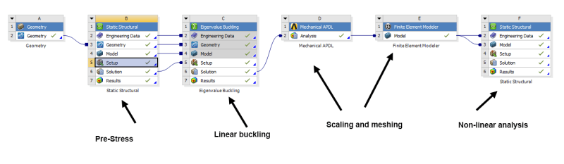
Setup in Workbench:

Capture_dmiehg.png


An example (not mine):
1-s2.0-S0263823116306048-fx1.jpg
 
Replies continue below

Recommended for you

In general if you want to carry out a buckling analysis using a nonlinear solver one could do the following:

- For buckling to be triggered physically (e.g., offset loads or imperfections), and not numerically by the solver, one can generate imperfections in the structure.

- One can apply imperfections directly on the mesh/model, or use scaled deformations (very small) from a linear buckling analysis that are added in small amounts again to the mesh/model (FE software can allow for the export of scaled eigenvectors/shapes from the post processor).

- With the small imperfections resembling the buckling shape/behaviour that you obtain in e.g., experiments, one can now run a nonlinear analysis to obtain the necessary results (e.g., buckling loads and perhaps post buckling strengths). Buckling will be triggered by the small imperfections.

I hope this helps.


Thanks for the reply sir!

Indeed - what I have done thus far is using the output from the eigenvalue buckling as 'imperfections' and using this geometry (scaled up) as input to a static, nonlinear analysis. However, what I am trying to achieve is to get an estimate for the strains that are present in that particular 'imperfect' geometry. Is there a way to do this with such a setup (or any other way)? As with the example image above - imagine having recreated the buckled shape as shown to the right (which looks visually similar to that of real the specimen to the left) - what are the strains?

Thanks again

Julian
 
No worries - you are more than welcome.

The initial imperfections created by the linear buckling solver are very small and only there to trigger the correct buckling mode as seen say in experiments for a certain set-up (as we said instead of having numerics triggering buckling in a nonlinear analysis, it is better to include small initial imperfections).

Once you run the nonlinear analysis and you go beyond buckling (post buckling), you can get stresses and strains. If you have used material nonlinearities (+geometrical) and you have gone beyond yielding (can be the case when you go beyond initial buckling), if you then unload (decrease the applied external load back to zero), you can get the residual stresses and strains (linear strains are recovered plastic are not). The resulting post buckled configuration after unloading should then hopefully match any experiments or tests, so you can then perhaps get an estimate of any residual stresses that are present in the unloaded post buckled structure from your FEA.


Status
Not open for further replies.

Part and Inventory Search

Sponsor