Continue to Site

Eng-Tips is the largest engineering community on the Internet

Intelligent Work Forums for Engineering Professionals

  • Congratulations waross on being selected by the Eng-Tips community for having the most helpful posts in the forums last week. Way to Go!

ETABS Earthquake Core wall Transferring causing very unexpected shear distribution

Status
Not open for further replies.

B_B012

Structural
Dec 7, 2023
7
Hi there,

I have a simple multistory building with a basement. There are a few transfer floors that need to transfer out columns and shear walls. The system is a two way slab supporting core walls and various other shear walls. I've taken my gravity loading from another program and then applied it in ETABS as a mass source. This allows me to use auto lateral feature in ETABs.

My approach from a vertical loading perspective is to design the slab for vertical loads using RAM concept. This is not an issue.

When using ETABS to conduct lateral analysis of the building, it produces very weird shear and moment distributions in pier elements under pure EQ cases. After playing around, adding rollers under the core walls, adding thick slab under the walls to simulate some rotational and vertical stiffness it still gives me results that I would not expect. I'm getting shear reversal up at floors where there should not be any shear reversal.

I don't want the slab to couple hence why i've modelled shell elements with low out of plane stiffness to simulate a membrane. I've tried adding some out of plane stiffness but its still not producing shears from what I expect.

Has anyone encountered this before? I noticed weird shears even under dead load from what I believe is the building tipping towards each other.

Any help would be appreciated as I've spent alot of time testing different things but no luck :(

Attached is my etabs model if you would like to have a look. I'm very interested in seeing how we can tweak a Etabs lateral only model to capture the forces on lateral load resisting elements.

Thanks so much!


 https://files.engineering.com/getfile.aspx?folder=2585a5f7-b3df-4891-820c-a434d5c66bb2&file=Tower2Test.e2k
Replies continue below

Recommended for you

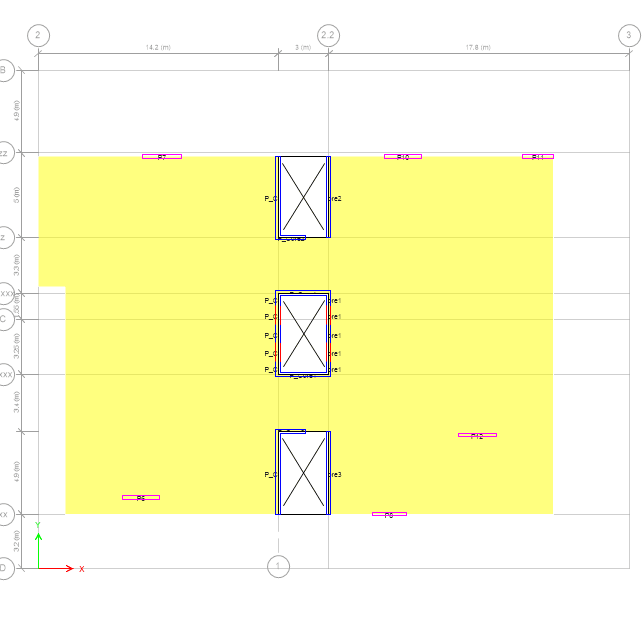
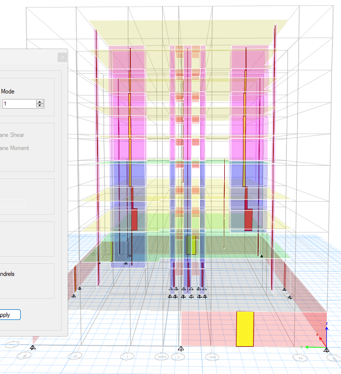
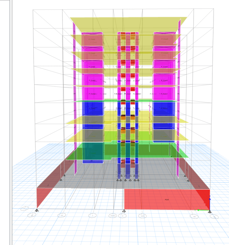
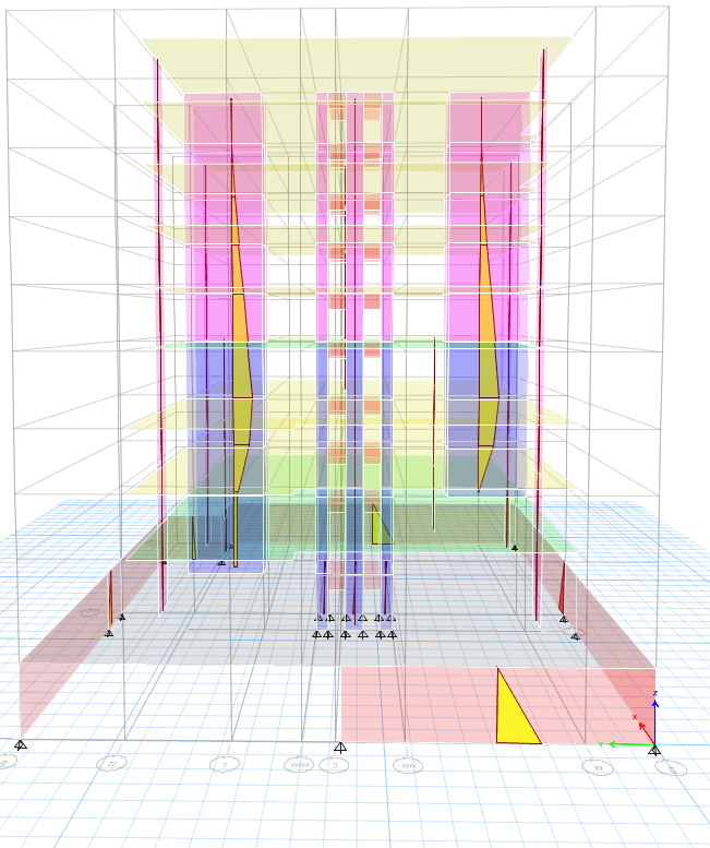
Can you post some screen shots of the odd pier forces and maybe some plan views of the building? Might be able to help debug with some more info.
 
Is it the interior / elevator core portions that might have a drop in shear at the ground floor?

If so, this is pretty common in analysis models like this. The exterior basement walls are so long and thick they're just going ao suck out all the shear from those interior walls. At least in a stiffness analysis.

Maybe for DESIGN you want to design those core walls for the same shear down at the basement level. But, the stiffness analysis is going to re-distributed at that level based on the lateral stiffness of your 600 mm slab at that level.

Or, is it the other shear walls that terminate at that 600mm slab? Just looking at the model, I assumed that those walls would continue down rather than terminate at the slab.
 
Typical_Plan_ql15mp.png
SFD_EQy_ah3sjj.png
Elevation_h2qb5y.png
BMDEQy_dday2r.png


Hi team!

Thats correct the core walls "Transfer" out at Ground level and level 1. They don't extend to the base. I would expect typical story shear steps all the way down and a cantilevered wall moment distirbution plot. There shouldn't be any shear reversal up the building other than central core that extends all the way to base (as there is a stiff podium). I'm not sure the best way to model this behaviour in Etabs.

I've tried adding rollers under core transfers and it attracts too much lateral load for some reason which doesn't make sense.

Note Columns are all pinned hence not modelled as doesn't contribute to lateral Etabs model.

Regards
 

So, what is likely happening is that the Core walls become stiffer for shear at those levels. Why? Take a look at the deflection diagram for EQ in the Y direction and I think it will make more sense.

There is basically no rotational support at the Ground Floor level. You're just sitting on a flexible slab. So, those walls rotate a lot at their base. Making them a lot less rigid than the elevator core walls that go all the way to the basement.

Think of this of this at three columns that are all in the same shear line and vertically supported. The columns are connected with struts (really your diaphragms) so that they deflect the same at each floor level. One of those columns is pinned at the ground level for deflection but free to rotate. Another is pinned at the 1st floor level and free to rotate. The other one is a cantilever fixed at the basement level. The closer to the pinned support for one of the columns, the more of that shear will transfer into the core column that is rotationally supported. In fact, those pinned columns are being HELD BACK by the one with the fixed support.

 
I'd send you the picture of the deflection which makes this make more sense..... Unfortunately, the computer I use to run ETABS doesn't like Eng-Tips today for some reason.... [sad]
 
Thanks for the explanation!

So i'm thinking the appropriate modelling methodology be to use a rotational spring and vertical spring at the base of the wall? I feel this has to be very accurate otherwise im taking too much load away from core

Thanks
 
I'd say model the flexibility of the slab in the model.

As a design engineer (albeit one who has never been the EOR for a structure this significant), I'd say that there is a design decision here. I'd continue a column or two down into the basement those walls.
 
My assumption is that you do have columns below those discontinuous shear walls, but you're not modeling them because you only wanted to model the lateral-force-resisting system? The lateral behavior of the building is very dependent on those columns so they should be modeled. With the computing power available today, it is really best to model the gravity framing because the gravity elements will actually interact with the lateral system and it's important to know how they interact (such as these columns or the outrigger effect on the normal tower columns)
 
This looks like it could be a soft story condition.
 
bones206 said:
This looks like it could be a soft story condition.

I didn't notice before that it looks like the core on the right side stops one level above the podium which definitely makes the story above the podium look like it would be a soft story
 
JoshPlumSE said:
The closer to the pinned support for one of the columns, the more of that shear will transfer into the core column that is rotationally supported. In fact, those pinned columns are being HELD BACK by the one with the fixed support.

Yes, I think this might be what is happening. The central core is creating a backstay effect on the left core. And then the podium is creating another backstay effect on the central core.
 
You really need to be modelling the L1 and ground floor slabs out of plane behavior, including all gravity columns. There isn't a complete load path without them, and more importantly, the stiffness of the discontinuous walls is not correctly captured. Garbage in, garbage out.

You should address the weak story concern immediately, because its not allowed in many jurisdictions. Regardless, all the supporting elements should be capacity designed for the demands.

Better yet, revisit your structural scheme and see if you can make it work without relying on discontinuous shear walls.

 
Thanks all!
I've now also modelled the columns in but not sure what the best way to model them as pin with (partial fixity?) As if we model out of plane stiffness of slab this results in slab coupling which will be hard to achieve and not really intended.

The way I think to get around it is modelling a thick slab with out of plane behaviour only on the transfered core wall area. But then that creates another issue where because the core walls say the left core and right most core transfer out at different levels,

Looking at Eq Y case (Inplane to the two out most cores), the right core that transfers out first "sucks out" all the load first because of modelling out of plane behaviour leading to in realistic loads in that core as it's now so much stiffer at levels above compare to that of the left most core which has the transfer out of plane slab modelled in at a lower level. Then the load will get dumped back onto the other core on the left.

Quite tricky from a modelling perspective so would be quite interesting to hear.
 
Status
Not open for further replies.

Part and Inventory Search

Sponsor