Hi,
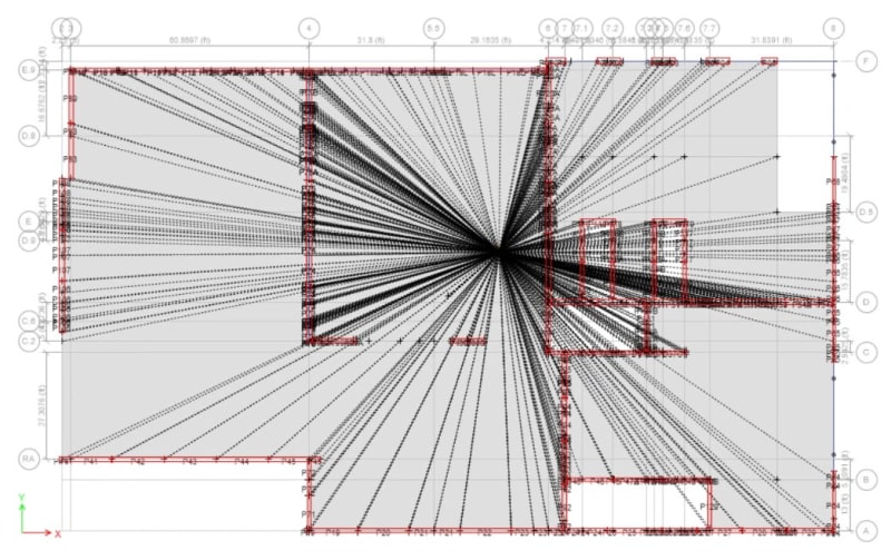
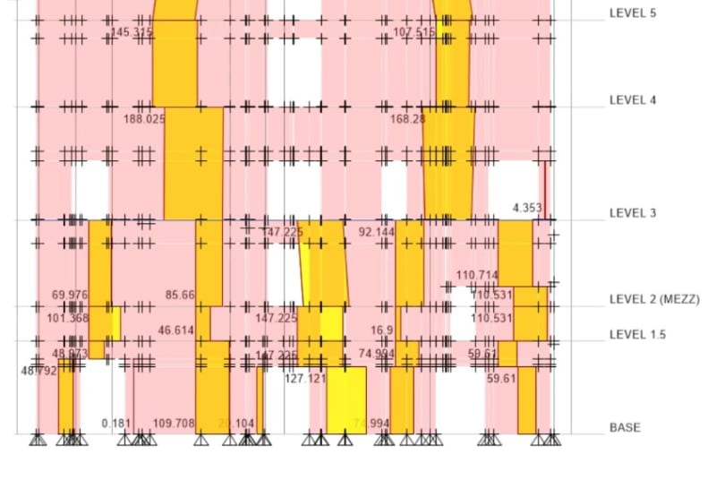
I wanted to get some feedback from ETABS users regarding the shear distribution due to rigid diaphragm approach. I am modeling a 13 elevated floors building that has horizontal precast panels from level 3 up, and then vertical panels below. The way I am modeling the joints is with a 1" gap between panels. I am noticing that the horizontal panels that sit on top of 5 vertical panels are not distributing the load equally between these panels, and almost always a large amount of force wants to go through the panel in the middle. Does anyone know what is happening? Is it normal for the most amount of load to be going mainly on the middle panel? At other elevations of the building I am having the same issue. Horizontal panels stitching vertical panels and then the middle one gets the most amount of shear load. There are stiffer panels (completely solid) that should be taking the largest amount of load but instead everything wants to be dumped in the middle one regardless if its less stiff or not. See images attached. The elevation I am showing is on Gridline 4.
All joints are properly connected to the diaphragm. The slab is modeled as a membrane with the "Rigid Diaphragm" special mesh option ETABS has.
If I tried to not connect the horizontal panels to that middle vertical panel, then the horizontal panels have a huge reversal and don't take as much load.


