Eng-Tips is the largest engineering community on the Internet

Intelligent Work Forums for Engineering Professionals

ETAP Motor Starting Study for 600kW Ball Mill 5

Status
Not open for further replies.

Ashdgee

Electrical
Jun 12, 2019
23
0
0
AU
Good day engineers, not sure if you use ETAP,

I am investigating the effect of starting a 3,3kV, 600kW ball mill for a gold mine.I am doing a dynamic motor starting study as we want to see the effect it has on the generator terminals.

ETAP has different load models that represent compressors, fans etc.These models are in the form a polynomial equation which is a function of Torque and Slip.I am not sure which load option to select (see pic) to represent the ball mill motor.Can anyone assist ?

See link for ETAP image
 
Replies continue below

Recommended for you

I think it unlikely that any of the ETAP standard load models match a ball mill. Here is an attempt to develop a load model mathematically. Electromechanical Dynamic Behaviour and Start-Up Evaluation of Tumbling Ball Mills; Weidong Lv ,1 Guoqiang Wang,1 and He Tian; Published 27 Sep 2018; If there is no clutch there the curve might be similar to constant torque. But the motor would need to be special design.
This is not very close to my wheelhouse, but perhaps this is enough to start some conversation.
More data is needed to take the question further.
Fred
 
I would consider the load to be constant torque.
I would calculate the inertia of the system.
From that I would estimate the starting time.
I have no idea how fast the mill turns and so no idea of the inertia.
I suspect that the inertia will be fairly low.
This site may help.
Link

Bill
--------------------
"Why not the best?"
Jimmy Carter
 
From what I've seen of ball mills, the chamber would have a certain amount of inertia, but at a very low speed. The balls and the charge in the mill would seem to work against the inherent inertia. Seems like a pretty high torque load with somebody's foot on the brake pedal all the time.
 
The problem with ball mills vs a simulation like ETAP is that the mill initially is a torque load that is dependent on rotation angle until the charge start to tumble. ETAP only simulates the torque vs speed as a curve. Best bet would be to use a torque peak right off zero speed and then drop down to a more constant torque type of load curve. The initial torque to start rotation will most likely be over 100% or rated torque. How much depends on the design of the mill.
 
I would look at another way.
If the mill is able to "find its own level" when unpowered, it will tend to roll back until the surface of the charge is mostly level.
When the motor and the mill are started, the torque may be less but build up to running torque as the charge approaches the angle of repose.
This however does not take into account any inertia which is unknown to us at this time.
I anticipate quite low inertia.
However, if the inertia is much higher than I anticipate I will accept your assessment Lionel.

Bill
--------------------
"Why not the best?"
Jimmy Carter
 
the ball mill motor are generally slip ring type with LRS stator and starting current is limited to 1,5 times to rated current ,

the ball mill provided with speed torque curve.
 
I worked on a number of autogenous mills. (Ball mills without the balls)
Each mill driven by two 3000 HP WRIMs at 13 kV.
They were started with liquid rheostats.


Bill
--------------------
"Why not the best?"
Jimmy Carter
 
This was somewhat unique Lionel.
The mills were rated to operate with approximately 100 tons of charge.
They were about 30 feet in diameter and were driven by a ring gear around the circumference.
There were significant mechanical savings by driving with twin motors.
Using WRIMs had the twin advantages of much easier starting and no issues with sharing the load.
There were six of these mills for a total HP of 36000 HP.
Add to that the large number of flotation cells.
I am aware that the synchronous motors on ball mills are often used to correct the facility PF.
In this instance PF correction was accomplished by two large synchronous condensers in a dedicated standalone building.
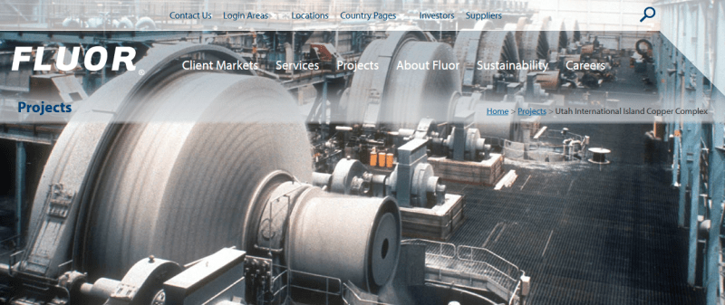
image_lzk453.png

Fluor said:
Fluor built the existing Island Copper complex in 1971. The concentrator has a capacity to process 33,000 tons of ore per day.

Island Copper's six autogenous grinding mills, each 32 feet in diameter and 14 feet in length, comprised the largest totally autogenous grinding circuit in the copper industry at the time. The grinding mills convert the ore into approximately 230,000 tons annually of copper concentrate and 1,800 tons of molybdenum concentrate.


Bill
--------------------
"Why not the best?"
Jimmy Carter
 
The biggest mill I've seen was around 30,000hp with the field poles mounted around the outside of the mill. It was over 40 poles. Driven by a large cycloconverter. Wish I could remember the details better. The torque calculated out to a ridiculously high value.

 
Status
Not open for further replies.
Back
Top