simulation_engineer_2022
Mechanical
Hi everyone!
I have a model of tube forming operation using Abaqus/Explicit and I need to evaluate two geometrical parameters of processed tube:
1. Ovality of tube cross-section, which requires measurement of minimum and maximum diameter of the machined tube;
2. Curvature of tube's longitudinal axis, which generally is how much tube's axis differs from straight line;
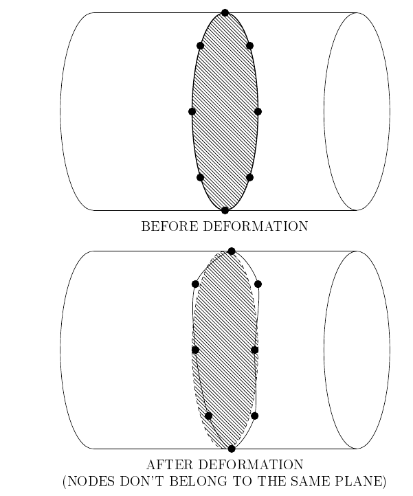
Does anyone have an idea how to measure these parameters from deformed mesh using Abaqus/Visualization module or 3rd party software/algorithm? Or maybe what additional options should I include in model to get these outputs. The undeformed mesh is quite regular, due to simple shape of a workpiece, and nodes of each circular cross sections lie in the same plane, but after treatment nodes can be shifted both in radial and axial directions and no longer lie in the same plane.
Ideally the process should be possible to automate using Python scripting. The kinematics of process itself shouldn't be important, but if you are interested it is cross-roll straightening of a tube. The element type could be shell or 3D solid, it doesn't matter for now, the key is the principle of measurement.
Thanks in advance!
I have a model of tube forming operation using Abaqus/Explicit and I need to evaluate two geometrical parameters of processed tube:
1. Ovality of tube cross-section, which requires measurement of minimum and maximum diameter of the machined tube;
2. Curvature of tube's longitudinal axis, which generally is how much tube's axis differs from straight line;
Does anyone have an idea how to measure these parameters from deformed mesh using Abaqus/Visualization module or 3rd party software/algorithm? Or maybe what additional options should I include in model to get these outputs. The undeformed mesh is quite regular, due to simple shape of a workpiece, and nodes of each circular cross sections lie in the same plane, but after treatment nodes can be shifted both in radial and axial directions and no longer lie in the same plane.
Ideally the process should be possible to automate using Python scripting. The kinematics of process itself shouldn't be important, but if you are interested it is cross-roll straightening of a tube. The element type could be shell or 3D solid, it doesn't matter for now, the key is the principle of measurement.
Thanks in advance!