Dear all,
I have tested a concrete beam that is embedded into layer of gravel (100 mm thick). I have looked only at vertical direction. The accelerometers are positioned on top of the beam and the impact was applied as close as possible to the positioned accelerometers. In total I have used 10 accelerometers along the beam length and I have applied an impact close to every accelerometer. In total I have applied 5 impacts per impact location and later I have averaged the results from all five.
In Figure 1 you can see the the distribution of the accelerometers (blue circles) on top of the beam. The accelerometers are glued with cyano acrylate adhesive directly to the beam surface.
Figure 1: Accelerometers distribution

Also these are the details of the used equipment setup.
Impact hammer: sledge hammer with plastic tip from Piezotronics Model type PCB 086D50, 5,5 kg.
Sampling frequency: 10 kHz
Accelerometers type: IEPE Accelerometers Dytran 3225M24 and Dytran 3333A
Data logger: Campbel Scientific CR9000X
I will show you only part of the data I've got for accelerometer P1 and for impact applied as close as possible to P1. Usually, I have records from all the accelerometers P1 to P10 when the impact is applied at P1.
My interest is to get the first four translational modes up to 500 Hz.
I have attached you the force auto spectrum, with coherence and one drive point FRF plot for impact at point P1 and recording at P1. Also, I've attached the Bode plot and plot of Imaginary and Real parts of FRF.
Figure 2: Force auto spectrum
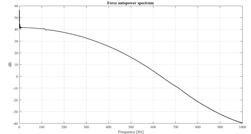
Figure 3: FRF magnitude, Coherence and Force auto spectrum
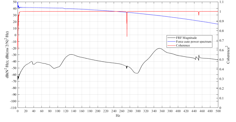
Figure 4: Bode plot for drive point FRF at P1
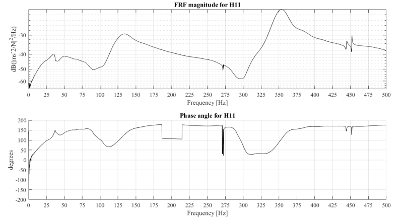
Figure 5: Magnitude, real and imaginary plot for drive point FRF at P1
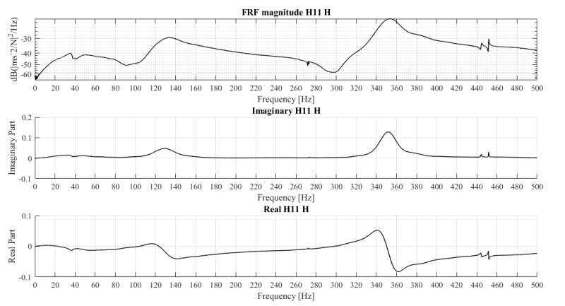
Figure 6: Imaginary plots of FRFs for point P1 (H11) to P10 (H110) when the impact is applied at P1.
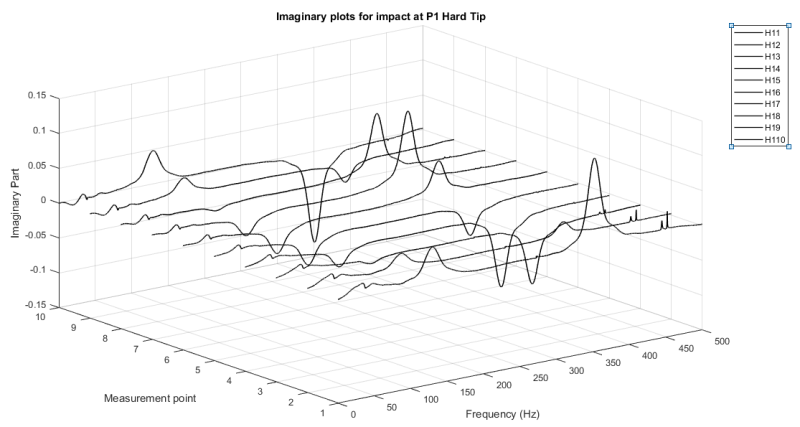
From Figure 6, 3 modes in total are visible. 1st and 2nd bending at around 130 and 350 Hz; and 1st translational rigid body mode at 30Hz respectively. According to the literature for the beam I have tested I should obtain also the second rigid body mode that corresponds to rotation, but in my test I couldn't get it. Do you think is it possible to obtain the second rigid mode as well?
As you can see the FRF curve under 100 Hz is not that clear in Figure 3. I have one peak around 30 Hz and something between 40 and 60 Hz. The second peak that should correspond to the second rigid body mode should be also very close to the first one, but it is not visible from the FRF plot. Do you have any suggestions how could I improve the testing in order to get this second mode? Do you think I can get the second mode at all?
Also, my concern is related to the phase shift at location of resonant frequencies. According to the books it should be from 0 to 180, but I don't have this as you can see on Figure 4. It's also not even close to the perfect phase plots I have seen in the literature. Also, I don't know what the dip between 180 and 210 Hz means in the phase plot. And what about the phase plot up to 100 Hz for the rigid body modes?
The next step in my work is to extract the modal data from the FRFs plots. But until then I would like to be sure that the FRFs I am using are the best ones and most representative for my setup.
Any suggestions on my testing would be of great benefit.
Also if I could get some comments on my plots would be of great help.
Many thanks,
Emina
Emina B.
I have tested a concrete beam that is embedded into layer of gravel (100 mm thick). I have looked only at vertical direction. The accelerometers are positioned on top of the beam and the impact was applied as close as possible to the positioned accelerometers. In total I have used 10 accelerometers along the beam length and I have applied an impact close to every accelerometer. In total I have applied 5 impacts per impact location and later I have averaged the results from all five.
In Figure 1 you can see the the distribution of the accelerometers (blue circles) on top of the beam. The accelerometers are glued with cyano acrylate adhesive directly to the beam surface.
Figure 1: Accelerometers distribution

Also these are the details of the used equipment setup.
Impact hammer: sledge hammer with plastic tip from Piezotronics Model type PCB 086D50, 5,5 kg.
Sampling frequency: 10 kHz
Accelerometers type: IEPE Accelerometers Dytran 3225M24 and Dytran 3333A
Data logger: Campbel Scientific CR9000X
I will show you only part of the data I've got for accelerometer P1 and for impact applied as close as possible to P1. Usually, I have records from all the accelerometers P1 to P10 when the impact is applied at P1.
My interest is to get the first four translational modes up to 500 Hz.
I have attached you the force auto spectrum, with coherence and one drive point FRF plot for impact at point P1 and recording at P1. Also, I've attached the Bode plot and plot of Imaginary and Real parts of FRF.
Figure 2: Force auto spectrum

Figure 3: FRF magnitude, Coherence and Force auto spectrum

Figure 4: Bode plot for drive point FRF at P1

Figure 5: Magnitude, real and imaginary plot for drive point FRF at P1

Figure 6: Imaginary plots of FRFs for point P1 (H11) to P10 (H110) when the impact is applied at P1.

From Figure 6, 3 modes in total are visible. 1st and 2nd bending at around 130 and 350 Hz; and 1st translational rigid body mode at 30Hz respectively. According to the literature for the beam I have tested I should obtain also the second rigid body mode that corresponds to rotation, but in my test I couldn't get it. Do you think is it possible to obtain the second rigid mode as well?
As you can see the FRF curve under 100 Hz is not that clear in Figure 3. I have one peak around 30 Hz and something between 40 and 60 Hz. The second peak that should correspond to the second rigid body mode should be also very close to the first one, but it is not visible from the FRF plot. Do you have any suggestions how could I improve the testing in order to get this second mode? Do you think I can get the second mode at all?
Also, my concern is related to the phase shift at location of resonant frequencies. According to the books it should be from 0 to 180, but I don't have this as you can see on Figure 4. It's also not even close to the perfect phase plots I have seen in the literature. Also, I don't know what the dip between 180 and 210 Hz means in the phase plot. And what about the phase plot up to 100 Hz for the rigid body modes?
The next step in my work is to extract the modal data from the FRFs plots. But until then I would like to be sure that the FRFs I am using are the best ones and most representative for my setup.
Any suggestions on my testing would be of great benefit.
Also if I could get some comments on my plots would be of great help.
Many thanks,
Emina
Emina B.
