Continue to Site

Eng-Tips is the largest engineering community on the Internet

Intelligent Work Forums for Engineering Professionals

  • Congratulations waross on being selected by the Eng-Tips community for having the most helpful posts in the forums last week. Way to Go!

Excluding Peak Stresses From FEA Results 5

Status
Not open for further replies.

Paulettea

Mechanical
Sep 28, 2016
101
Dear All

As per ASME BPVC Sec. VIII-2 Par. 5.5.6 in order to perform ratcheting analysis using an elastic method, it is necessary to calculate primary plus secondary stress range and peak stresses must be excluded in the process. When the FEA results of a linear elastic model are available, the software does not exclude any type of stress. In fact, the software does not have any idea about peak stresses or stress categories at all. Is there any trick to understand what portion of stresses belong to stress concentrations?

Furthermore, for protection against plastic collapse there is a need for separation of primary and secondary stresses. The code clearly mentions that this process of stress categorization needs significant knowledge and judgement. Here again obtaining FEA results seems to be an easy part of the story and the troublesome stress categorization is a main issue. However, I need to know if there are guidelines in order to do stress categorization after obtaining FEA results. What are the tricks if there is any?

Warm Regards
 
Replies continue below

Recommended for you

Hi Paulettea,

If I recall correctly, in order to perform an elastic analysis for ASME VIII-2, you must first do a stress linearization, and when you do that, you gonna have membrane stresses, bending stresses and peak stresses. So, you automatically have the peak stresses, so it is just some scripting to eliminate them.

On your second questions, there is some guidance on the code, but I agree that most of it is not really sufficient for complete understanding. However, most pressure vessels books have a topic on this subject, google is also full of references on this.
 
It's likely that I will run afoul of the site management with these links (commercialism). However, you are definitely in need of training on this topic. The questions that you ask are very good questions, but can only be adequately addressed in the context of in-depth technical training provided by expert-level engineers. Training next May and September.


I agree with TGS4 about the assessment of the quality of the question. I confronted with the same problem a few times.
My opinion is the same with victorpbr. Some FEM programs (I use Abaqus) stress linearization tools classify the stress types.

This may help you:
 
Stress linearization is (somewhat) easy. Coming up with valid and validated SCLs is more art. Categorizing the linearized stresses that come from an analysis requires substantial experience and expertise. See 5.2.1.2.
 
I do not use Abaqus, so I do not know the internals of it, but in ANSYS last time I used it, I had to do a script for linearization because it does not use the same methodology indicated by the ASME code, so I recommend you checking this also on the help files.
 
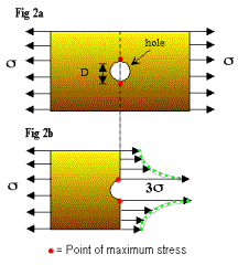
I know in stress linearization peak stresses can be developed. Even in Ansys workbench there is a tool that can do this automatically(although I have doubt if it performs correctly). However, my question is different. Sometimes, when you use an SCL through thickness of a shell the results may be misleading. Consider the following case:

stress_concentration_w8tkwt.gif


If you consider an SCL through the thickness of the plate at the edge of hole then what you will see is that after linearization, the membrane stress component in the direction of the shown stress will be 3σ.
Here, if the results from linearization of stress is considered after the stress σ reaches the value Sy/3 then the membrane stress will be Sy and therefore a plastic collapse will occur. However, in reality there will be no plastic collapse since just as you move away from the edge of the hole the stress will fall down below the yield stress.
Now, what is the decision? If you consider the peak stresses are those that develop due to stress concentrations then you have to say that the membrane stress is σ and the peak stress is 2σ.
If you consider the peak stress to be that derived from stress linearization then there will be almost no peak stress and the membrane stress is 3σ.

Warm Regards
 
The point of maximum stress is the peak stress. It looks like the 3σ shown in your diagram is referring to the peak stress, not the membrane stress.
The membrane stress is the average stress along the SCL. At the ends of the plate it is shown to be exactly σ.
The membrane stress across the ligament on either side of the hole looks like it is slightly greater than σ.
 
Your latest query is more in the vein of "where do I put my SCL (and how do I orient it)?" Are you trying to make an analogy with this situation of a nozzle in a shell? If so, then it would be better to just use that geometry.

In this specific case, a SCL oriented perpendicular to the screen at the edge of the hole would not be appropriate. The proper SCL would be vertical on either side of the hole. The membrane stress will likely be very close to σ*(L_plate)/(L_plate-D).
 
MrPDes, the problem that I have shown here is a very famous problem in the theory of elasticity. It shows that for sufficiently wide plates -with a hole in center- that are subject to a unidirectional stress field, the stress concentration factor is 3. As you have mentioned the stress can be considered to be peak stress since it is developed due to stress concentration. However, if you consider a through thickness SCL just at the edge of the hole (perpendicular to the drawing plane) the average stress will be almost 3σ. This may lead to the conclusion that since the average value of stress over the SCL is 3σ then this is the membrane stress.

TGS4, as you have guessed I am talking about the appropriate location of an SCL. You say in this specific case the SCL perpendicular to the screen is not appropriate. Then you change the SCL direction from the edge of the hole to the edge of plate. This is a very simple case and you can simply choose another path to exclude the peak stress effect on membrane stress. However, in a more complicated case (like the vicinity of a nozzle edge in a cylindrical shell) it will be no longer an easy job to do.
TGS4 suppose that instead of a flat plate, a cylinder with a hole is considered with a uniform axial stress. What will be the appropriate SCL then? This time it cannot be a line that comes from the hole edge and goes in the hoop direction.

Warm Regards
 
Please draw a sketch with some proposals for an SCL, and I'll provide some feedback.
 
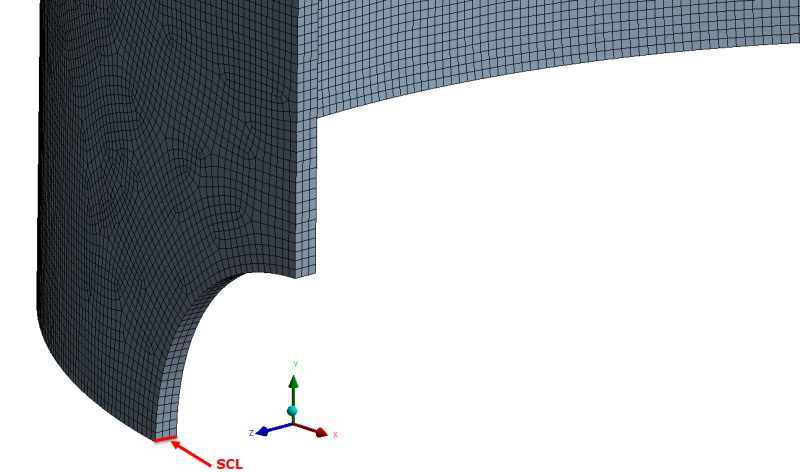
TGS4, below is a sketch of what I mentioned in previous post. The SCL that I have shown (to my eyes) seems to be the only acceptable one in order to evaluate the state of stress at the edge of the hole. If the average of stress component in Y-direction over this SCL is considered as the membrane stress then the effect of stress concentration on this average value is neglected.

cyl_jzhnil.png
 
Paulettea,

There would be no need to produce an SCL and conduct linearization at the location you have shown, because there is no bending stress or peak stress. There is only a 'local' membrane stress P[sub]l[/sub] which is limited to 1.5×(S[sub]y[/sub]/1.5) = S[sub]y[/sub].

Away from the hole is the General membrane stress P[sub]m[/sub] which is limited to S[sub]y[/sub]/1.5.

The hole has the effect of intensifying the membrane stress, for which the stress intensity factor would be P[sub]l[/sub] / P[sub]m[/sub]. This particular example of a stress intensity does not contain any peak stress or bending stress. It is purely membrane. The hole would need to have a nozzle neck or something similar to produce bending or peak stress.

If this local membrane stress at the edge of the hole exceeds its allowable, then reinforcement needs to be added in the form of a thicker shell, reinforcing pad etc.

Also, the greatest local membrane stress would occur at the other corner shown on your FEM model (90° around the hole), where the hoop stress would cause the SCF to approximately double in value compared to where the SCL is currently shown.
 
I'm not entirely certain that I would categorize the membrane stress in that perforation (an isolated hole as such would typically only exist in a perforated shell) as primary local. Depends on the loading. Depends on a lot of things.

When in doubt as to the appropriate categorization, refer to 5.2.1.2.
 
MrPDes, the cylinder that I modeled is not a pressurized one, I mentioned earlier that it is just under a uniform axial load. Suppose the cylinder is long and the hole is just at the middle of the shell. That is why I considered the SCL at that location. But I agree that if t was a pressurized cylinder the SCL has to rotate 90 degrees. From what you have said I come to this conclusion:

If the increase in the stress is due to discontinuity then the membrane stress obtained from linearization is local membrane stress. And the stress due to nonlinear distribution over an SCL is peak stress.

Therefore, in order to exclude peak stresses I do not need to know anything about the source of stress and just stress linearization is enough.

What is the reason for the following recommendations in the code:
ASME BPVC 2015 VIII-2 Par. 5.A.3 (a) said:
For the evaluation of failure modes of plastic collapse and ratcheting, Stress Classification Lines (SCLs) are typically located at gross structural discontinuities. For the evaluation of local failure and fatigue, SCLs are typically located at local structural discontinuities.

Why should I search for plastic collapse in gross discontinuities and local failure in local discontinuities? In the cylinder with a hole is the SCL on a local or a gross discontinuity?


Warm Regards
 
I think that if you linearise across your shown SCL the result will be a total stress shown as a horizontal straight line. This would indicate a local membrane stress of same value as total stress, a bending stress of zero and a peak stress of zero.

The conclusion is that with experience you would know that there was no need to linearise (Of course it is nice to check just in case something unpredictable shows up). Perhaps there would be a small amount of radial distortion causing a small amount of bending, however there are no sharp inside corners to produce peak stresses.
Your example doesn't produce pressure vessel type stresses so as per TGS4's advise, you might want to refer to 5.2.1.2.
Perhaps you should read Annex 5-A which has allot of information relating to your questions.

The answer to your final question is included in 5-A.3(a). I suspect that you need to research and gain experience learning the difference between plastic collapse and local failure and how each of these failure mode relates to the size and nature of a particular discontinuity. With experience a pattern will begin to emerge.
 
MrPDes said:
I suspect that you need to research and gain experience learning the difference between plastic collapse and local failure and how each of these failure mode relates to the size and nature of a particular discontinuity.

Humour me. Please explain to me what's the difference between plastic collapse and local failure. How would you diagnose "local failure" at such a hole, as opposed to "plastic collapse".
 
TGS4, what do you mean? Do you mean there is no difference between local failure and plastic collapse?

As far as I know they are totally different modes of failure.

Local failure is different from plastic collapse whether it is in this geometry and loading or any other one.
 
MrPDes, I know there is difference between local failure and plastic collapse. I am looking for some logic behind the recommendation in 5-4.3(a). It says SCL for plastic collapse and ratcheting is better to be on gross discontinuity. It says SCL for local failure and fatigue is better to be on local discontinuity.

OK, why do we need SCL for fatigue. Do we have to perform linearization for fatigue at all?
 
SCL for fatigue is to ensure that you have elastic shakedown. If you don't, then you have to add some modification factors.
 
Status
Not open for further replies.

Part and Inventory Search

Sponsor