Continue to Site

Eng-Tips is the largest engineering community on the Internet

Intelligent Work Forums for Engineering Professionals

  • Congratulations KootK on being selected by the Eng-Tips community for having the most helpful posts in the forums last week. Way to Go!

Existing Wood Beam - Reinforce with Steel Saddle

Status
Not open for further replies.

SarBear

Structural
Mar 14, 2022
38
Would like to get some feedback on this. Client has an approx. 27' long LVL beam across his family room to bear the second floor joists above. The beam currently breaks over a bearing post at approx. 9'. The client would like to remove the bearing post.

Another engineer wrote a report for the client saying that the post can be removed and a 1/4" steel saddle is to be installed at the bottom of the existing beam, basically "cupping" the beam up to the bottom of the existing floor joists. The city plan reviewer asked for some calculations showing that this solution works, but the engineer said he can't do that. Client came to us to ask if we could do it. By transforming the proposed steel saddle into an equivalent wood beam I feel that I'm able to prove that it would work for bending and deflection. If the wood beam was continuous then it would work in shear on its own without the steel saddle. But it isn't continuous as noted on the drawing below.

So what do you all think? Is this a fool's errand? Obviously we could either remove the beam and replace it, or cut off the bottom part of the existing beam and put in a new dropped steel beam. But if this saddle could work the client would prefer it for obvious reasons. I'm just not sure I have the tools or know-how to figure out what happens at that break in the beam. Any thoughts or advice would be greatly appreciated.
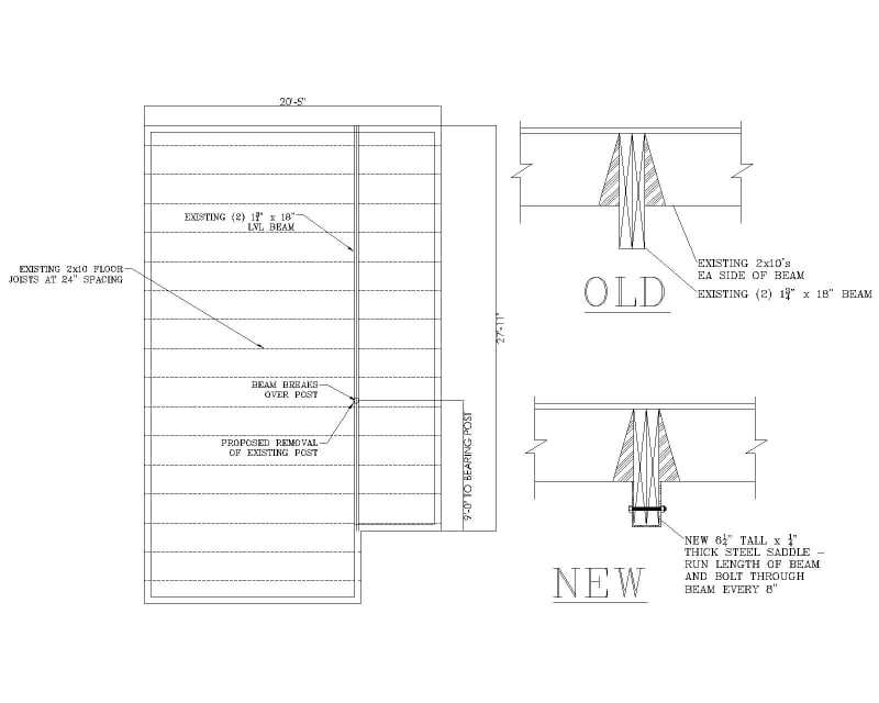
Steel_Saddle_tyzvad.jpg
 
Replies continue below

Recommended for you

I've occasionally reinforced wood using steel BAR stock with nominal attachment, relying on adhesive. You may have difficulty getting design values for this and approach it as an engineering problem... not a textbook one. Rather than using bolts, you might want to look into 'glulam rivets'.

-----*****-----
So strange to see the singularity approaching while the entire planet is rapidly turning into a hellscape. -John Coates

-Dik
 
At the splice location you no longer have a wood section that follows the strain compatibility assumptions needed for wood beam design or for composite section analysis. You might get some compression or something on the top side of the wood but that is dubious at best.

From a strength perspective, you could check shear and bending at that location specifically and perhaps the steel section meets the requirements by itself.

From a deflection standpoint, I think its hosed. The discontinuous wood beam will contribute to overall stiffness in a weird fashion that is difficult to comprehend (let alone calc out.)

Now if you could guarantee that the wood is fully composite on both sides of the splice maybe you could think of it as (3) separate beam sections connected with a rigid splice.

Like
Composite saddle composite
[--------------XX---------------]

Where the saddle has a really short length.

Im just spitballing ideas from analysis, TBH I'm not a fan of this solution I would seek a new member that can carry all the load. Seems like you could do a decently shallow steel beam beneath existing beam.

As an aside, I like how the original engineer was like 'Oh ya this would work easy peasy, but I cant put the calcs on it, cant do that'. This is not a good look for an engineer If I was the B official I'd be leary of them moving forward (at least).
 
In order to make the steel actually take load you need to shore to remove dead load deflection and account for all the slip you will get from the bolts. Nails or screws are much better for sistering connections than bolts for this reason.
What kind of shear flow are you getting for the bolts?

All in all I think it's a bit of a fool's errand.

[Edit] I missed the part about the beam not being continuous over the post. This is a bad idea.
 
Thank you all for your input. I didn't like the idea either but I wanted to do some due diligence before coming out with a knee-jerk NO.

driftLimiter said:
I like how the original engineer was like 'Oh ya this would work easy peasy, but I cant put the calcs on it, cant do that'.
Lol yeah...the wonderful world of residential engineering.
 
I seriously doubt you can get a 27 ft span to work out with that saddle - even if the LVL was continuous.
Best to rip it out and install the proper beam.
 
Agree with everyone above. I gave it no chance of working with just the saddle and then when realizing the beam is not continuous, fuhgeddaboudit.

Put in a new W14 or W16 and call it a day.
 
Replace the beam with a new W steel beam with web packed. You will need to remove all of the hangers from existing joists. Cut them shorter because the W beam will be wider. Then install new face mount hangers on the existing joists. I detail this all of the time. If you have a lot of head room, then just add a new beam next to it below the joists.
 
I vote fool's errand.

Slip in the connection will neuter any desired composite behavior in the absence of the adhesive that dik mentioned. The thing might not collapse but may wall sag significantly after the post is removed.

I wouldn't do this in my own house.
 
Status
Not open for further replies.

Part and Inventory Search

Sponsor