Eng-Tips is the largest engineering community on the Internet

Intelligent Work Forums for Engineering Professionals

Expansion Joint connection to the crude oil tank 2

Status
Not open for further replies.

Amir Sedieqy

Military
Aug 11, 2020
10
0
0
IR
Hello,
I have started similar threat in Pipelines, Piping and Fluid Mechanics engineering Forum, but Littleinch suggested to start it here.
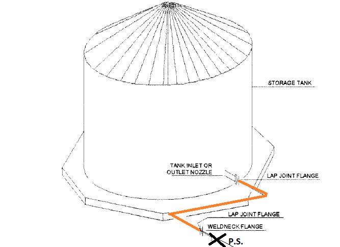
In a piping system connected to the outlet of a crude oil tank, process man has located the expansion joint after the valve which is connected to tank's nozzle. Since this expansion joint is located after the valve, it must be able to withstand the design pressure of the piping system. However, if this expansion valve were located before the valve, and was connected to the tank's nozzle, it should have only withstand the pressure due to fluid height in the tank, which is one-twentieth of the piping design pressure. I was wondering whether it is practical to connect the expansion joint directly to the tank's nozzle. I'm aware of the risk of not being able to isolate the tank in case of expansion joint failure. however, since this expansion joint is only for settlement issue, its life cycle is very low. Therefore, I'm not sure that its failure is likely. I appreciate it if could share your similar experience.
 
Replies continue below

Recommended for you

Dear Amir Sedieqy (Military),

I am not sure i got the picture... If the thread is for the outlet of a crude oil tank, the pressure should not be problem .. The flow should be with gravity ( to the inlet of pumping st. etc.)..

The common practice is that, the piping system together with supports shall be designed for settlement so as not to impart significant loading on the attachment to the tank or tank shell. The flexibility could be provided with expansion loop, joint or may be with bellows . Personally i prefer to reroute , provide some offsets etc.

Will provide a sketch showing the proposed piping , tank , sizes etc and predicted settlement?

Another point, as per the forum policy ; double posting is not allowed. If you get the respond that you are looking for, delete the other thread.
 
That's my fault. Prob best to concentrate on this forum.

I think what he means is that if you isolate the tank at the tank (inlet) valve then the pressure in the piping can increase or at least be rated to a value much higher than the tank head by a considerable margin.

I think the issue is finely balanced between one side being higher rated and the other the risk your bellows will leak and you can't isolate the tank.

I would always go for being able to isolate the tank, even if it means another valve.

Remember - More details = better answers
Also: If you get a response it's polite to respond to it.
 
The first object past the tank flange should, in my opinion, be a valve. If you want to put an expansion joint after and protect it with another valve, go for it. Be sure to evaluate the need for thermal relief.
 
Thank you guys,
Based on what you said, an isolating valve is unavoidable, which means expansion joint shall have the same design pressure as the rest of the line.
 
Belman makes universal expansion bellows marketed specifically for tank settlement


Eagle Burgmann also makes somewhat shorter metallic expansion joints for crude oil tank farm applications:


(Interestingly, the .PDF EB flyer for Storage Tank Expansion Joints shows pictures of both an Isolation Valve AND a check valve mounted on the tank. Clearly, if the EJ fails, the check valve is supposed to stop reverse flow ....)

I agree with the statements of IFRs above, you cannot simply add the EJ ... You must include an additional isolation valve

Additionally, the external fire case must be evaluated by a competent Fire Protection individual. There must be information available from the vendor on the performance of the EJ in the event of a fire.

In my opinion, considering the additional cost of the EJ AND the additional isolation valve AND years of additional inspection and maintenance, the usage of additional loops of piping may be a more attractive choice when dealing with tank settlement


MJCronin
Sr. Process Engineer
 
What about for the use of lap joint flange with zig -zag spool ?
Excerpt from ( PROCESS PIPING DESIGN HANDBOOK )

lap_joint_flange_fkthhy.jpg
 
Hturk,

That's good for the initial fit up as it allows you to fit the pipework to match the elevations. However it then gets welded in place so when the tank settles which is what the OP is talking about it doesn't move and puts forces on the nozzle.

Having said that the Zig zag spool piece will reduce loads and add a lot of flexibility so might be a good idea for the OP.

Remember - More details = better answers
Also: If you get a response it's polite to respond to it.
 
I agree with HTURTAK ..... with some reservations

But I disagree with Littleinch ..... Some rotation will exist at the faces of the lap-joint flanges which will mitigate the tank settlement.

HURTAK's scheme will work only with lap-joint flanges, not other types

However, the owner must periodically monitor the lap-joint flanges for leakage as the tank settles ..

Any body else ???

MJCronin
Sr. Process Engineer


I have edited my post ... Assume we have a PS at location shown with X and assume the tank experience a substantial amount of settlement ( say 100 mm) .. If the outlet pipe size is small , with the zig zag spool , the settlement could be compensated with flexibility of piping..

However, if the pipe size is large enough , the zig zag spool will exert abnormal torsion to the tank outlet nozzle and remaining piping .


In case of the use of LAP JOINT FLANGE, the torsion effect will be reduced with the friction failure of back -up flange and gasket..


Mr CRONIN, i just see your post .since i was writing my respond.. But i fully agree for the monitoring of the lap joint flange but in case of substantial settlement, may be just extra tightening of the bolts could stop if there is small leak. Bu a pink star for your comment..
 
MJC - I must admit you might be right in practice, but I've never seen torsional slip of a bolted flange being used as a stress relieving measure.

But yes, in essence what we've been trying to tell the OP is that there are other ways to accommodate the tank settlement, but tbh, I wouldn't be building tanks I expected to settle by more than 50mm. settlement is rarely even across the tank and you need to fix the foundation, not the pipework...

Remember - More details = better answers
Also: If you get a response it's polite to respond to it.
 
I've participated in several tank and piping jobs where long term tank settlement is simply a fact of life. Stainless steel bellows type expansion joints are very common at these sites, from 4" to 36". It's pretty easy to specify an expansion joint of the appropriate length to accomodate the expected settlement. We tend to spring the joint in the opposite direction as the settlement so over time the piping moves to a neutral position, then continues to the other extreme. Site monitoring is needed to watch the slow movement over time. The piping has a support and sometimes an anchor just past the expansion joint, other times the first pipe support is spring loaded.
 
Amir,

I notice your field tag is "Military". If this is a project for the US military or on a US military site, they would typically follow the aboveground tank standard AW 078-24-27. This standard calls out ball joints to accommodate tank settlement, which are located between the process headers in/out of the tank and the tank isolation valves as others have mentioned.

Just another potential design to consider.
 
IFRS - you've done a lot more tanks than me and indeed many tanks do start to settle over time, but usually when you know the predicted settlement is significant, there should be ground improvement works to prevent excessive settlement.

I guess the issue is what is seen as "excessive"....

Remember - More details = better answers
Also: If you get a response it's polite to respond to it.
 
There are locations where no amount of soil improvement will eliminate settlement, or the cost to get to or create adequate bearing strata is too much to bear, often in coastal areas. I remember specifying metal bellows expansion joints 60" long and springing them up 3" to account for 6" of long term settlement. In those cases we formed notches in the tank foundations to make it easy to airbag jack the tank in the future to re-level it. There was always a valve on the tank flange and a valve somewhere on the other side of the joint. The expaneion joint typically experiences only the head in the tank. There was typically thermal relief across the joint.

Back to the OP's original question, since settlement is not the only reason an expansion joint failure could occur, a valve on the tank flange is mandatory in my opinion. Also, the only way the joint could experience higher than tank head pressure would be if the tank valve was closed and the valve on the opposite side of the expanseion joint was open. This situation can be avoided pretty easily...
 
I have used no expansion joint in this kind of applications. You may need an L type pipe route with a bit long length after the bend. You may have to add a bottom support just before the bend to take the valve weight. You may change direction after sufficient length to overcome the settlement. I applied this with 16-20 inch pipes. It worked with reasonable stresses and deflection required.

Everything depends on the the value of settlement and the concrete base, if available. Sometimes the entire area can be on the same concrete base. This applications are used in the mining mineral processing industry mostly since they need concrete base all around.

The oil tanks mostly on the concrete ring base, and tank base plate is on the compacted soil. These tanks may require 100-150 mm of settlement. In this case you may use the system in the first paragraph, and some constant spring hangers may be required to overcome settlement stresses on the pipe.

 
Status
Not open for further replies.
Back
Top