PipeNewbie
Petroleum
Guys,
Firstly congrats on an insightful and knowledgeable forum. I'm just starting a career as a mechanical engineer doing pipe stress analysis and have read a few of threads, which have been very useful.
I have a question that I'm struggling to get my head around.....
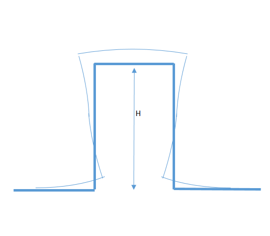
Based on the guidance in Kellogg's "Design of Piping Systems", the optimum expansion loop has a K1 value of 0.5, i.e. an expansion loop length equal to 1/2 the distance between supports. This makes sense to me as it creates equal minimum deflection at each of elbows in the loop and allows a minimum leg length (minimising steel required).
Why in practice do you tend to see expansion loops that don't correspond to a K1=0.5 and tend to be small in length relative to the total length of pipe? Sure this just results in a greater displacement at the elbows and longer leg length that would be required?
I've attached a sketch if that doesn't make sense.
Cheers
PipeNewbie


