Eng-Tips is the largest engineering community on the Internet

Intelligent Work Forums for Engineering Professionals

  • Congratulations waross on being selected by the Tek-Tips community for having the most helpful posts in the forums last week. Way to Go!

Explain high stress spot in bolt joint with femap/NX Nastran

Status
Not open for further replies.

upzheng

Mechanical
Apr 2, 2013
4
0
0
CA
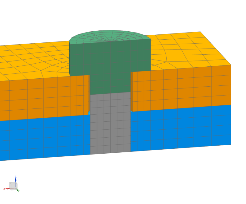
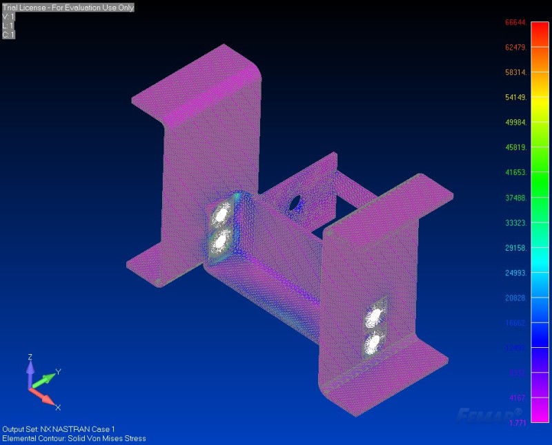
I have a 3 pieces assembly jointed by bolt. I use RB2 in Femap/Nx Nastran to simulate the bolt. Two side parts are fixed. One part is under the upper right load from the two free hole. After run the analysis, I get results shown in attached picture.
1_hdhzud.jpg


I can see the bolt squeezing the side piece. so there is high stress area. This high stress is much high than the yield strength 36ksi.

2_detail_vggvlk.jpg


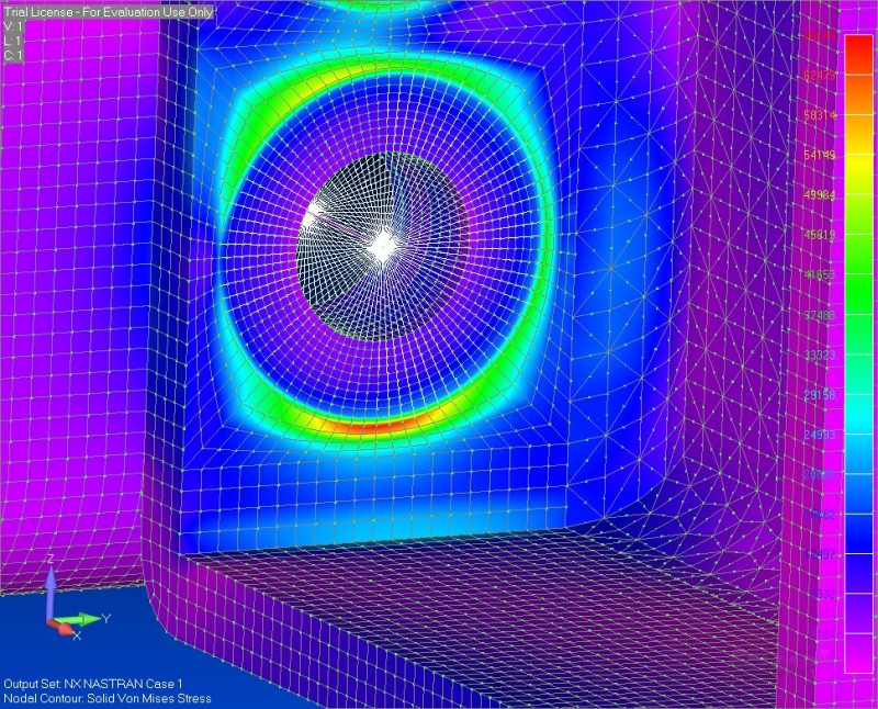
The results show is the max value of nodal stress. if I use average stress of elements, the high stress is down to 48.4kis from 66.6.
3_detail_of_average_ipstxe.jpg

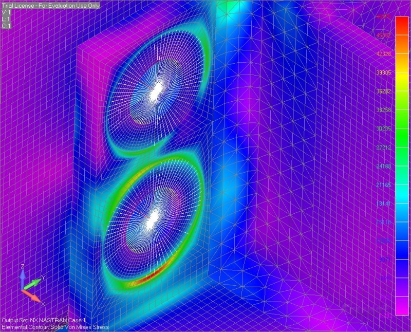
it is still higher than yield strength. In real case. we know it could be safe. but not 100% sure. and we also want safety of 2. Could anybody help me the interpret this case? Is the result correct?
I would appreciate if somebody could help me out.
 
Replies continue below

Recommended for you

Are you putting a preload on the bolt or just using the RBE2 to rigidly connect the 2 parts? If you're not using it for preload, is that really the best way, or should you define a bolt connection region? I am horribly inexperienced at Femap (just look at my other threads and you'll see), so maybe consider this a bump for your thread so that someone else will take a look [tongue]
 
Hello,
it is simple reason: you can't evaluate stress where is connection to RBEs (or you can but results are very unrealistic[dazed] )
RBEs are rigid elements, their stiffness is unlimited therefore they cause artificial stress peaks.

Let me suggest how to proceed:

Ask a question: Do I really need to evaluate stress/strain result for the bolt connection?

if NO
- simple, because the goal of your task is something different that bolt itself. Of course, you can still f.e. check the stress for the bolt body, if the stress is still during the external loading still under Yield strength).
There are even some guidelines that say that you can evaluate stress f.e. regions that are 2 elements far from RBE2 legs, but this is too specific - depends on mesh density, structure, loading etc, not useful for general problem.

if YES
- than you should consider different bolt model, avoid RBE2's (even RBE3's). Very suitable is solid model with the bolt body and head (and nut if there is), and define a frictional contact between the bolt head and plate.
This is what I mean:

bulk_study_fem1_rgtp6x.png


Hope it helps,

Jan

With best regards,
Dr. Jan Vojna
Lead Engineer Development

Siemens, s.r.o.
 
my 2c ... this is driving FEA down a deep mine shaft. there are lots of reasons why the FEM might be showing unrealistically high stresses local to load transfer points.

let the FEA tell you the load on the bolt, then use traditional hand calc to show the load is good.

another day in paradise, or is paradise one day closer ?
 
Status
Not open for further replies.
Back
Top