Continue to Site

Eng-Tips is the largest engineering community on the Internet

Intelligent Work Forums for Engineering Professionals

  • Congratulations cowski on being selected by the Eng-Tips community for having the most helpful posts in the forums last week. Way to Go!

Explain pressures created by fluid flow through small orifices 1

Status
Not open for further replies.

TI-89

Mechanical
Nov 10, 2020
3
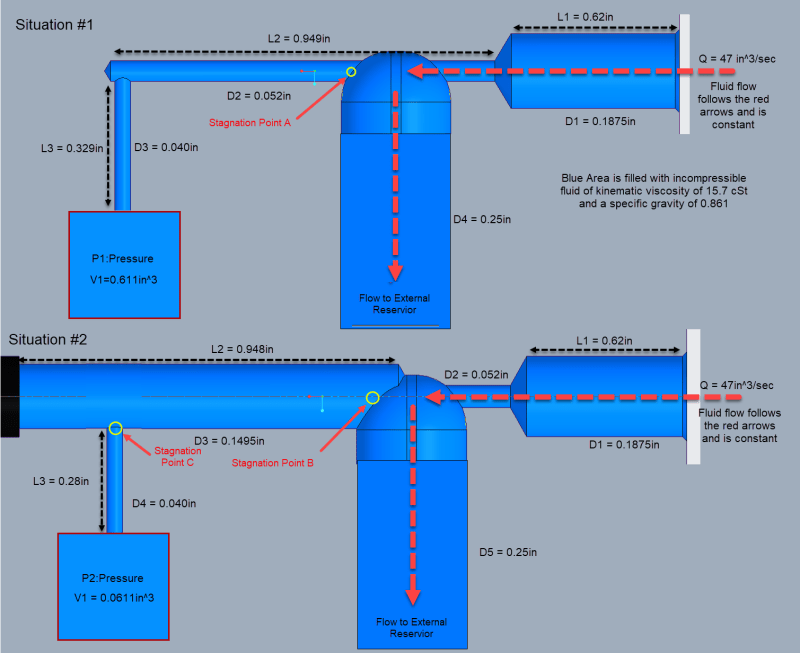
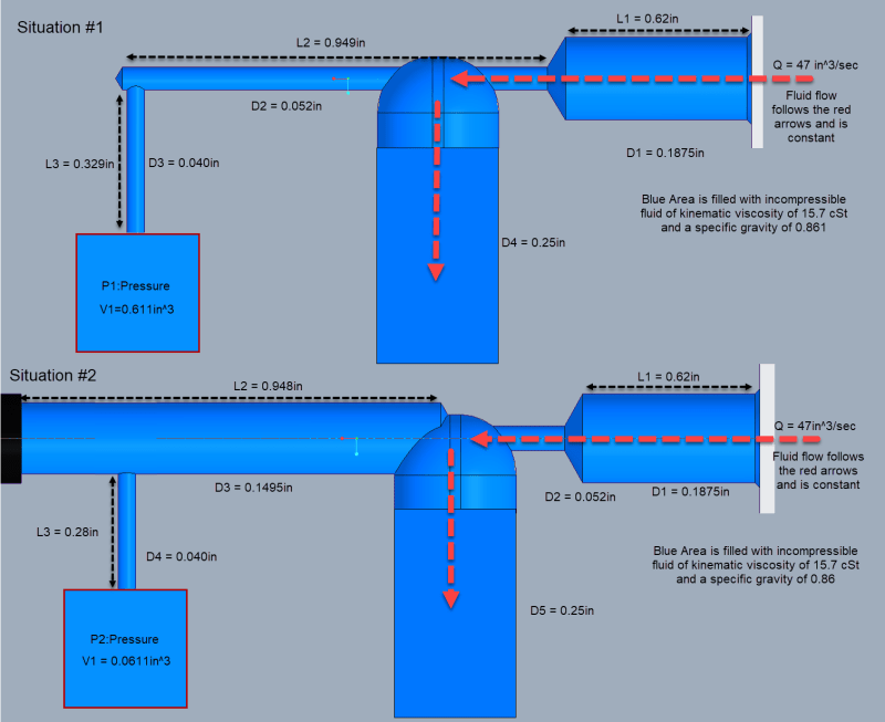
So my question is in relation to fluid flow and pressure. In my pictures below you can see that i have two similar situations. Fluid flows in from a large reservoir at a constant rate through a control orifice. It follows the red arrow and flows around a 90 degree angle into a tube. Up to this point both scenarios are relatively the same. We have a pressure tap in both scenarios that differ in size.

Scenario #1 has a small long orifice (0.052in in diameter) that feeds another 0.040in hole in the manifold and then a small volume were the pressure is measured.

Scenario #2 has larger diameter orifice (0.1495in in diameter) that feeds the 0.040in hole into a similar small volume where pressure is measured.

What i would like to understand is: why is the pressure in situation #1 (P1) higher than the pressure in the situation #2 (P2)?

Wouldn't opening up the holes increase the pressure in volume V1? I have literally tried this by drilling out the tap in scenario #1 to make scenario #2, but it drops the pressure. I have even found that making the orifice smaller increases the pressure. What am i missing here?

Flow_Orifices_e7c6nw.png

Situation #1 Small Orifice Pressure Tap Situation #1 Small Orifice Pressure Tap
Situation #2 Large Orifice Pressure Tap Situation #2 Large Orifice Pressure Tap
 
Replies continue below

Recommended for you

What on earth is this?

What is causing P2 to rise? Is it a fixed volume?

Is the pressure in P2 just a static pressure and this whole thing is liquid filled?

Is there any actual flow in these micro branches?

what exactly is going on in that elbow?

Remember - More details = better answers
Also: If you get a response it's polite to respond to it.
 
Is P1 the pressure of a pitot tube measurung the fluid flow, and P2 the pressure of a pitot tube measuring no velocity? That would explain it.

Good Luck,
Latexman
 
The pressure resulting from the flow turning 90 degrees may be influenced by the corner geometry as affected by the large and small orifice passage diameter intersecting the 90 degree turn.

Ted
 
LittleInch said:
1. What is causing P2 to rise? Is it a fixed volume?
2. Is the pressure in P2 just a static pressure and this whole thing is liquid filled?
3. Is there any actual flow in these micro branches?
4. what exactly is going on in that elbow?
1. It is a fixed volume.
2. P2 is a static pressure but is being influenced by the dynamic pressure at the start of the micro branches. (i think they are acting like pitot tubes). The whole system is filled with fluid.
3. There is no flow in the microbranches
4. I think the flow path has a lot to do with why the pressures are different. But i am trying to nail down a solid theory as to exactly why and then i will test it.

Latexman said:
Is P1 the pressure of a pitot tube measurung the fluid flow, and P2 the pressure of a pitot tube measuring no velocity? That would explain it.
I was thinking that the microbranches may be acting like pitot tubes, but i was unable to find much on pitot tube diameters influence on pressure. Looking at the picture below do think that the tube in situation #2 is to large? If it was large enough to allow fluid flow then the stagnation point could move from Point B to Point C. Does this make sense? When i was originally considering that they are pitot tubes i was thinking that the stagnation points would be at points A and B on both situations. Maybe it was wrong to make this assumption?

hydtools said:
The pressure resulting from the flow turning 90 degrees may be influenced by the corner geometry as affected by the large and small orifice passage diameter intersecting the 90 degree turn.
I did consider this as well. I was thinking of it as the chimney effect. The high velocity flow around the 90 degree elbow creates a low pressure zone at the start of the microbranches. This would effectively try to pull the fluid out of the micro branches and lower the pressure at P1 and P2. Would the diameter of the microbranch effect the pressure significantly?

Maybe it is a combination of the pitot tubes and chimney effect. I am right now just trying to wrap my head around what is most likely occurring. Thanks for the comments

2020-11-10_12-08-27_mcncy0.png
 
Well, 47 in^3/sec flow through a .052 hole gives a mean velocity around 1844 ft/sec - that's damn fast ("booking" in the vernacular). Yes, a geometry change in the corner may affect how much of that 1844 ft/s velocity gets converted to total pressure from the jet. And boring out the .052 hole changes the incoming velocity, so you don't have the same scenario in your description as what exists in Scenario #2.
 
If in fact the entry into the elbow is 0.052 in then velocity is actually 17,000 ft/sec.....

This whole thing is rubbish.

Remember - More details = better answers
Also: If you get a response it's polite to respond to it.
 
How you get 17,000 ft/sec? My calculation result agree with btrueblood, Just curios.
 
Area is 0.0021 in^2

Flow is 47 in^3/sec

Velocity = (volume /sec) / area

Which gets to 22,000 (my error was this was inches/sec).

So this is 1,865 ft/sec or 565m/sec.

So apologies, I'm more used to using metric...

But either way this is just a nonsense post.


Remember - More details = better answers
Also: If you get a response it's polite to respond to it.
 
All i am sorry, I gave the wrong flow rate. I attempted to simplify the question that i was asking and accidentally used the total flow of the system. The majority of the total flow 47 in^3/sec is bypassing the section that i am concerned about.

The actual flow rate at the inlet orifice is 3.876 in^3/sec which has a velocity 1824 in/sec or 152 ft/sec through the 0.052" orifice. I apologize for the confusion here, as it detracted from the original questions of what is occurring after the inlet office.
 
Still very high velocity and we still don't really understand what is happening here with these very simple diagrams. We need really detasiled drawings of what the inside of these things looks like.

How about some proper diagrams / drawings / pictures??

A high velocity jet impinging on a surface is a lot different to normal flow in a tube.

Remember - More details = better answers
Also: If you get a response it's polite to respond to it.
 
Hmm. There's enough info. to make some fairly simplistic sketches of likely flow paths in the corner, enough to explain a difference in pressure recovery in the left hand pressure sensor port.

I fired up my old-fashioned CFD (Cranial Fluid Dynamics) solver and generated the following images. In both pictures, the flow exiting the .052 orifice undergoes a turn because it is a scarfed nozzle (nozzle with an exit not perpendicular to the centerline). How much of a turn is debatable, but any turn in the exiting jet means that the parallel .052 port in the first image is not going to see much pressure recovery from the impinging jet, it instead samples a recirculation zone in the upper corner of the .25 passage. In figure 2, the larger, offset lefthand passage allows for more of the .052 jet flow to be intercepted, i.e. the pressure recovery could reasonably be higher than in Fig. 1 where less of the jet impinges on the mouth of the left hand passage.

Bottom line, he has data. Presumably whatever measuring device(s) used to take that data are similar and well-calibrated, and other factors (temperature, pump rpm, phase of the moon) were accounted for. An ounce of test data is worth hundreds of hours of CFD runs (the real kind) and my Cranial Fluid Dynamics is worth about 1/100 of a real CFD run.

EDIT: oops, re-read the OP's first post. He's claiming the opposite, i.e. he has data showing Fig. 1 generates higher pressure at the sensor? Well, again, data trumps CFD.

Fig. 1:
Capture_chidn1.jpg


Fig. 2:
Capture2_uvlzdr.jpg
 
Status
Not open for further replies.

Part and Inventory Search

Sponsor