Continue to Site

Eng-Tips is the largest engineering community on the Internet

Intelligent Work Forums for Engineering Professionals

  • Congratulations waross on being selected by the Eng-Tips community for having the most helpful posts in the forums last week. Way to Go!

Eye bolt contacting area 1

Status
Not open for further replies.

drodrig

Mechanical
Mar 28, 2013
260
Hi there,

We have to lift a heavy plate, it has existing threaded holes to screw in eye bolts.

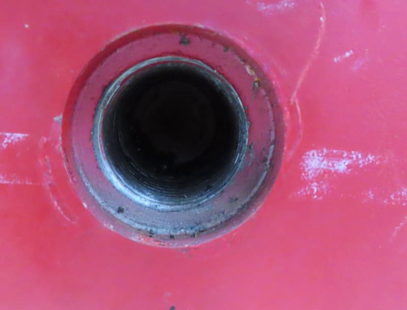
The thread is an M64, but it is counterbored with a diameter of 80mm and the counterbored surface is not flat.

The contact area of the M64 eyebolt is 120mm.

So the surfaces touching are from 80 to 120mm. Here a sketch showing it. One image is worth 1000 words...

m64_jmp1to.png


Is the contact area enough to use the maximum load capacity of the eye bolt?

We will also use it on the side of the load and pull at 90º

I was thinking to manufacture a washer to fill the gap, but since it is very irregular (and not flat) and I am afraid it will stick out and then only touch it and not the area of the big diameter.

Maybe a washer made of rubber? It could stick out a bit, then when screwing in the eyebolt it will deform and maybe help a bit increasing the area?

Are these counterbored holes normal to use with eyebolts?

thanks
regards,
 
Replies continue below

Recommended for you

The arrow pointing to "not a flat surface".... that arrow should be pointing higher, right?

=====================================
(2B)+(2B)' ?
 
No. It is fine

The contact surfaces are flat

But the counter bored surface has an angle. Which makes difficult to "fill the gap" with a kind of washer (so it can reach the contact plane to increase the contact area).
 
I wouldn't use about a "fill" washer. Check the contact area and stress using the available surface. If less than yield you are o.k.
 
drodrig,

The face at the bottom of your pocket probably is drilled. Of course it is not flat. Who cares?

I assume your eye[‑]bolt has a rated lifting capacity. If it doesn't, get yourself a new eye[‑]bolt.

When you install the eye[‑]bolt, there will be a compressive stress on the [⌀]120mm/[⌀]80mm[ ]face, and a tensile stress on the screw that must not exceed the rated capacity of the eye[‑]bolt. As you lift, the compressive stress on the face will be reduced, and the stress on the screw will remain approximately constant. When your lift exceeds your installation clamping force, and all sorts of interesting and undesirable things will start to happen. If your pocket is deep enough, it will reduce your thread engagement to something less than what is required to achieve the eye[‑]bolt's rated strength. If your thread engagement is marginal, a washer will make it more marginal.

Don't think of this as a conventional bolted joint. Normally, we don't apply external forces to bolts.

This still is basic machine design. I would expect the failure of an M64 eye[‑]bolt to be catastrophic. Am I missing something here?

--
JHG
 

It might be important to understand how heavy is the "heavy plate".

It might be important to know how many eye bolts and the magnitude and direction of the loads on each.

 
Since the contact diameter of the eye bolt is larger than the c-bore, the presence of the c-bore is meaningless if you have adequate thread length contact. No need to try to fill it in. I am much more concerned about the force at 90º. Make SURE the eye-bolt manufacturer guarantees to you that it is rated for that lateral load.
 
Hi drodrig

Instead of the 80 diameter counter bore, why don’t you put a spot face onto the surface and then drill and tap your hole through the spot face, that way you solve the problem of the area under the contact is no longer.

“Do not worry about your problems with mathematics, I assure you mine are far greater.” Albert Einstein
 
Instead of worrying about the place where the eye bolt doesn't touch, maybe think about the place where it does touch.

Depending on the material of the "heavy plate", and how tightly the eye bolt will be tightened, crushing of the annulus is possible.

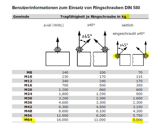
Lifting eye bolt ratings are stated for direct, in-line forces. They de-rate for other directions.

 
drodrig

typically a counter bore is for clearance for interference. a countersink would be preferred for the start of the thread to guide the drill & assembling the bolt.
usually depth of c'sink is 1-1/2-3 threads at the start of thread. just a suggestion. 2.5196(64 mm) is quite large. what is the rating and what is the load.
 
Thanks for so many answers

The plate is 8 tons heavy

We use 2 rings. One on each side such:
m64_uraidu.jpg


They can take 8 tons each, so we have a good safety factor

We can't machine / spot face the plate

How does one tighten it?

The plane containing the ring must be vertical, what if after screwing it in it stays horizontal.

I am thinking about making some big washers.

The pitch of the eyebolts is 6mm, i would do two types: 1.5mm and 0.75, so we can rotate them a quarter or an eighth
 
Here a picture if it helps

difficult to see it without a reference for scale

m64b_xanbvq.jpg
 
Hi

Why can’t you spot face the plate? So who puts the counter bore and tapped hole in?

“Do not worry about your problems with mathematics, I assure you mine are far greater.” Albert Einstein
 
The plate might have some radiation

If we remove anything from it we have to follow lots of regulations and collect every single chip

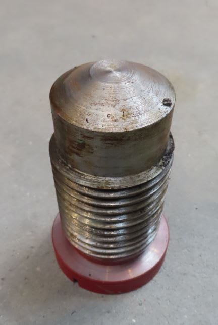
There is also a customized screw which fits here to close the gap. The plate is part of a magnet

cheers,


m64screw_g0udtv.jpg
 
Hi drodrig

Right now I understand.

“Do not worry about your problems with mathematics, I assure you mine are far greater.” Albert Einstein
 
drodrig,

That does not look like a good design to me, even though it is shown on your chart. Are the male and female threads tapped such that the eye[‑]bolts will be clamped in the orientation shown?

Under what tightening conditions are those eye[‑]bolts rated at eight tonnes? I am trying to understand how I would tighten a thread like that. Applying cantilever loads to a thread is never a good idea.

--
JHG
 
Have you considered a swiveling hoist ring? I'd think that would be a lot easier when lifting at an angle.
 
Hi,

We can't change the design. I don't know after tighten how the ring position will be. Washers with 1/4 and 1/8 of the pitch seem a good idea

The table with the forces comes from the DIN 580

Swiveling rings seems a great idea, but I'm afraid the people in charge of the assembly already have the "traditional" eye bolts

cheers,
 
Hi drodrig

The only problem spreading the load by using washers is you also reduce the amount of engaged thread and that’s not a good idea.

“Do not worry about your problems with mathematics, I assure you mine are far greater.” Albert Einstein
 
Status
Not open for further replies.

Part and Inventory Search

Sponsor