Eng-Tips is the largest engineering community on the Internet

Intelligent Work Forums for Engineering Professionals

  • Congratulations waross on being selected by the Eng-Tips community for having the most helpful posts in the forums last week. Way to Go!

Failed Splined Shaft, Interesting Fracture Zone 7

Status
Not open for further replies.

gearcutter

Industrial
May 11, 2005
683
AU
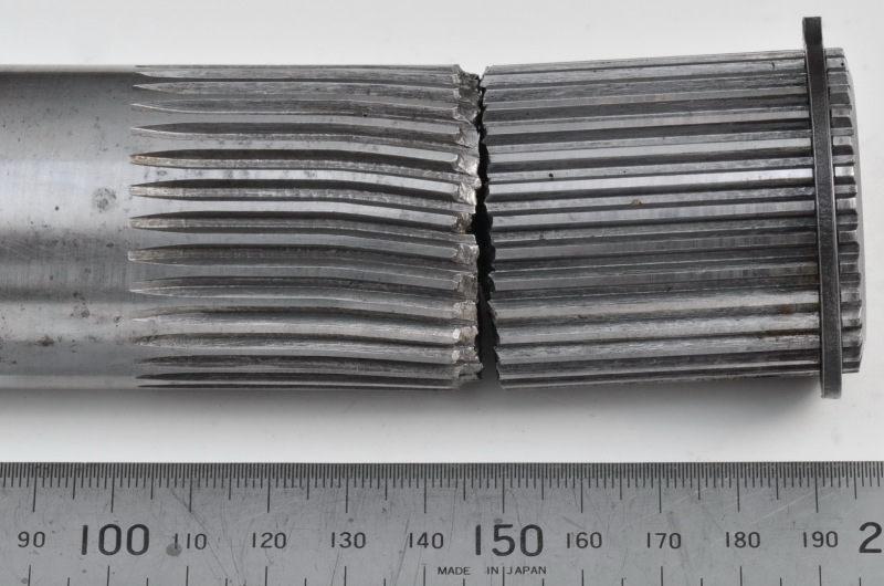
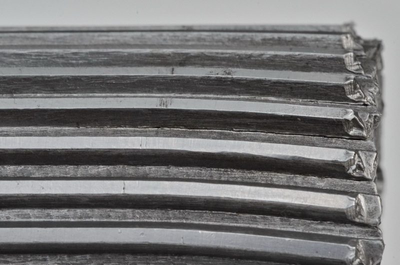
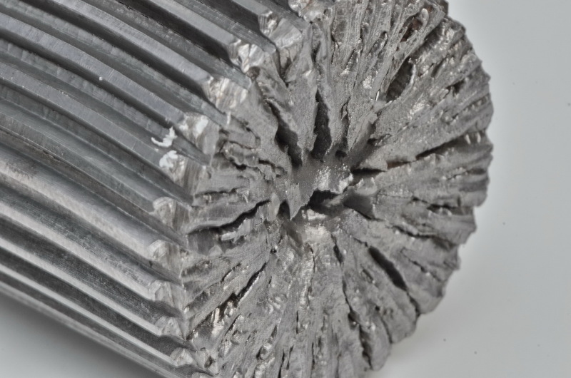
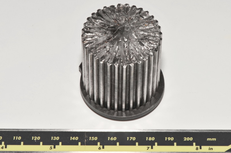
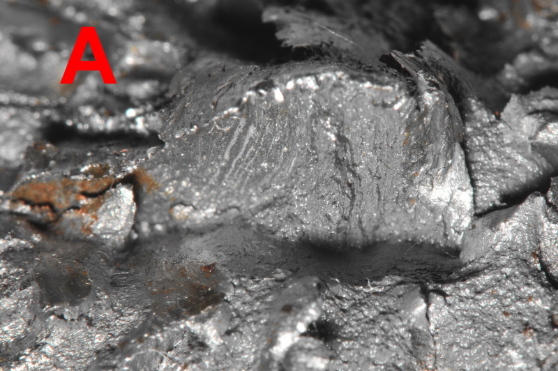
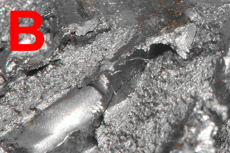
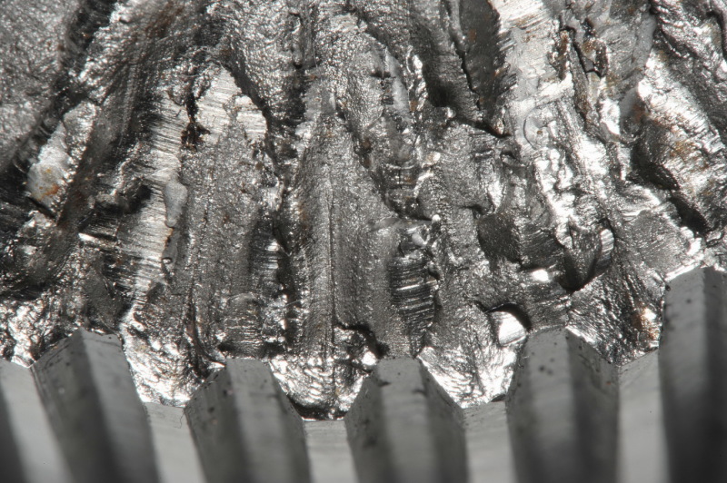
Here's an interesting failure of a small splined shaft that I'm currently investigating.
The Engineer's (hired by the OEM) final report simply stated that the incorrect material and heat treatment had been used.
The end-user has asked for a more detailed report along with recommendations.
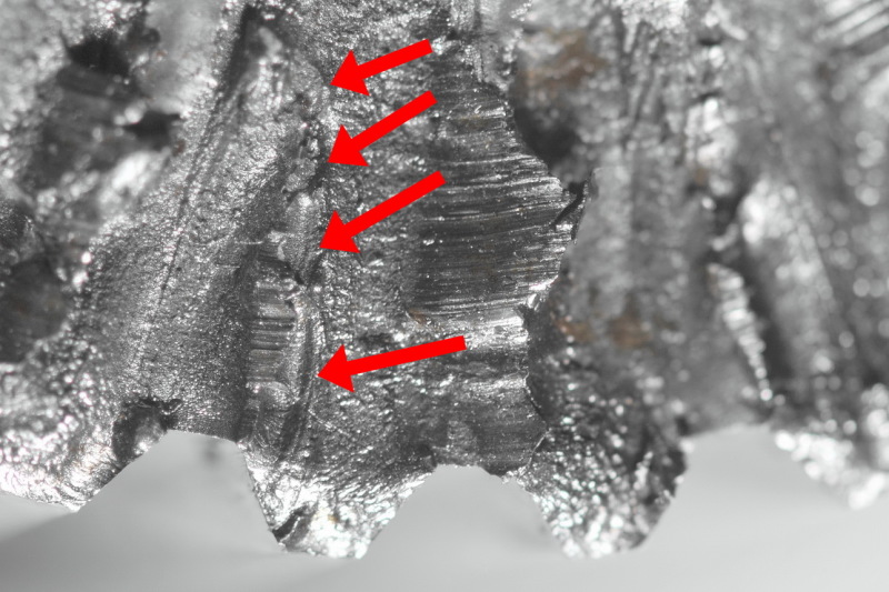
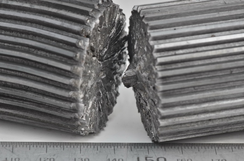
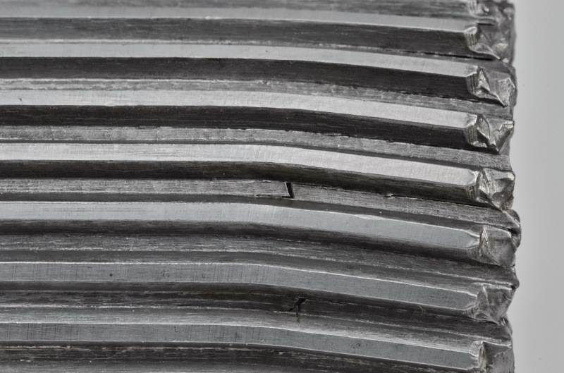
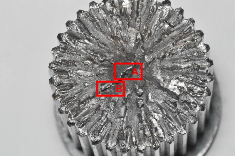
There's a lot happening on that fracture surface.

01_g9jia2.jpg


02_gdlbuv.jpg


03_gpx85f.jpg


04_x9wl8c.jpg


05_jxko5w.jpg
 
Replies continue below

Recommended for you

Definitely an unusual fracture for a splined shaft. Looks like a quick and clean break. Can't see any evidence of abuse on the tooth flanks adjacent to the fracture.
 
There's also no plastic deformation, the spline teeth run in a straight line along the length of the shaft.
What I find really interesting are the radial cracks running inwards, starting at the top lands of the teeth, the last images shows this.
I would have expected those cracks to start in the corners of the root profiles.
 
Were the spline teeth case hardened by nitriding or a similar process? In the last photo it looks like there might be surface cracks propagating out from the tooth tips near the fracture face.
 
No case hardening, only through hardened - 32-35HRC.
Material is 4140.
There are multiple failure modes occurring. Quite a few areas are showing signs of fatigue.
Unfortunately the uploading of images here isn't working out too well as the image quality is being significantly reduced [sad]

STA_1443c_uri9si.jpg
 
Hi

You might find this article of use
I think it's a rotating bend failure with its multiple radial cracks but we could do with more information about the spline in terms of service loads and the length of time it's been in operation.

“Do not worry about your problems with mathematics, I assure you mine are far greater.” Albert Einstein
 
Reversed torsional fatigue, common for splined shafts in the automotive industry.
 
Hi Gearcutter

I find it interesting that around the crack a slight corrosion is present.
possible suggesting a heat treat crack make have been present.
causing the ultimate failure as suggested by others.

I notice to, there is very little wear on the spline tooth flanks.
so no evidence of over load or wear fatigue. just my thoughts.

I know from my experience, 4140 if not harden and tempered correctly
will easily crack.
it would be interesting to do a met lab on a new finished part.

Mfgenggear
 
It would be handy to know more about the loading of this shaft.

Application? Pure torsion? Any bending? Load reversals? Torsional vibration? Also which section of the shaft length is subjected to the torque - does the failure coincide with the end of a female splined member?

je suis charlie
 
Thanks for the input everyone.
The purpose of the post wasn't a "how did this happen" type of enquiry.
The intent was to simply show those interested in the topic, an example showing (as corypad has correctly pointed out) the fracture zone of a reversed torsional fatigue failure.
 
Hi

Just to expand a little on that rotational fatigue, if you look at the second link I posted which also shows a similar failure on figure 4, it goes on to say that the angle of the fracture face relative to the axis of the shaft indicates whether there was a dominant bending force or tensile force involved.

“Do not worry about your problems with mathematics, I assure you mine are far greater.” Albert Einstein
 
I would agree with mfgenggear's assessment. The root cause was more likely a fracture produced during heat treat that propagated quickly.

Given the shaft cross section, relative spline tooth size, material properties, and condition of the spline tooth flanks, I don't see how the shaft could have failed in torsional fatigue (from either unidirectional or fully reversing load cycles). Even a combined torsional/bending LCF failure at the location shown would have produced some distress in the adjacent spline tooth flank surfaces.
 
Which is why I asked about location of the loading.

Beachmarks in the last image suggest torsional fatigue originating at the outer edge.

If the crack at "A" (a low stress area) was produced during heat treatment (which I doubt), it may have reduced the torsional strength of the shaft, enabling the fatigue failure, but I don't think the failure progressed from there.

je suis charlie
 
Even if the failure was due to torsional overload under LCF conditions, there would still be some evidence of distress on the spline tooth flank surfaces adjacent to the fracture face. The same would be true if the spline was subject to excessive bending loads.
 
The client was finally able to supply the other half of the failed component.
The pictures is certainly becoming much clearer.
The groove on the LH side is as a result of events that occurred post failure.


DSC_1470_mriujg.jpg


DSC_1471_gwmaae.jpg


DSC_1478_kgdzz9.jpg


DSC_1479_oderip.jpg


DSC_1474_o1ipu2.jpg
 
Now I can see the location of the loading. All becomes clear. Thank you.

je suis charlie
 
very interesting images. some of them show brownish discolorations suggesting that corrosion has occurred locally. since they are very local, it suggests that water may have entered through some cracks that developed. is there any explanation for that to happen?
 
romke - parts came out of a warm & wet environment (underground coal mine). As a result, some of the surfaces have started developing rust.
 
Thanks for the additional photos. Helps clarify things quite a bit.

Would it be possible to get more details of the associated components and how they were constrained?
 
Status
Not open for further replies.

Part and Inventory Search

Sponsor

Back
Top