Continue to Site

Eng-Tips is the largest engineering community on the Internet

Intelligent Work Forums for Engineering Professionals

  • Congratulations KootK on being selected by the Eng-Tips community for having the most helpful posts in the forums last week. Way to Go!

Failure of SS 316 stem in tension 5

Status
Not open for further replies.

Phil121324

Mechanical
Apr 16, 2020
9
Hi,

Hopefully i have posted this in the correct area, apologies if not- Send me in the right direction...

I am looking at the failure of a valve stem from a control valve, the stem has sheared during valve operation, the failure has occurred at the first thread at the bottom of the stem, the first weakest point, the thread connects the valve plug to the stem. In short the stem connects the plug within the valve body to the actuator, this then allows the control valve to control the pressure in the system. The stem material is SS 316, the valve works on a FWKO system ( at around 40 bar.

In normal operating conditions the stem sees very little tension (i am assuming failure in tension), if the valve is incorrectly setup the stem can be subject to tension, if the stem receives the full tension that the actuator can deliver the yield strength of the material is surpassed by around 20% however the UTS is still well within. As the stem is seeing tension my initial thoughts were not to be too concerned with the yield strength of the material and look at the UTS.

I have attached a photo of the failed shaft- can anyone shed some light on the type of failure or point me in the right direction. Could the failure be hydrogen embrittlement, a brittle fracture of a relatively ductile material.

thanks

Phil
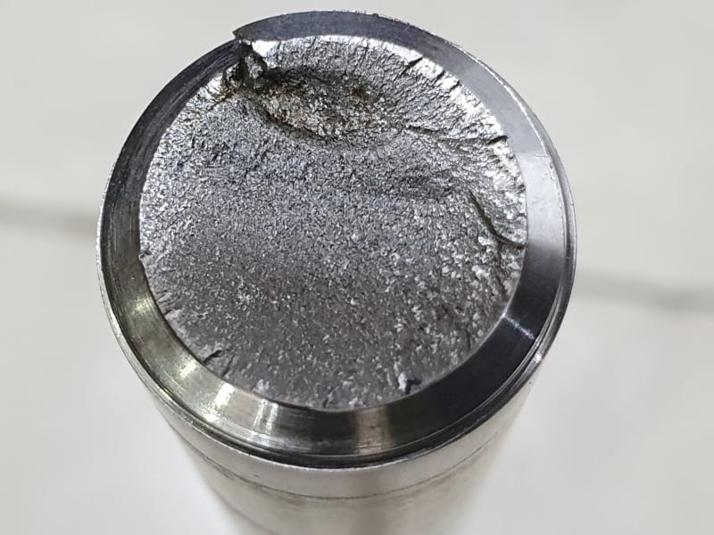
20200416_102025_n1gfme.jpg
 
Replies continue below

Recommended for you

I am thinking fatigue.
How often is the position of this valve adjusted? Even by a little bit.
Those are cut threads, not good.
And I am guessing that this stem does not have a straight section that is machined smaller than the thread minor diameter.
It would be interesting to take a cross section at the other end of the threads and measure hardness across the diameter.
Sometimes this material will be lightly cold worked to raise its strength, and that cold work only applies to a limited depth.
You will not get HE in 316 unless there are some serious secondary phases or inclusions.
That said, are there any (any at all) chlorides in this system?

= = = = = = = = = = = = = = = = = = = =
P.E. Metallurgy
 
I can't much help your failure analysis on the basis of one fractograph.
But this picture indicates a brittle characteristic to the fracture, so all fracture modes having this characteristic should be on the table. (Remember, 'brittle' is not a fracture mechanism but a characteristic.)
You mentioned the fracture occurred at the first exposed thread - you call it the weakest point. It is not weaker as such, just more vulnerable, because it is the point that sees maximum tensile stress from lateral forces imposed on the stem.
Always look for sources of bending loads, and don't get too hung up on precise calculations.

"Everyone is entitled to their own opinions, but they are not entitled to their own facts."
 
UTS is generally unimportant. A component is typically considered failed once it has yielded. Fatigue life will also be very short near yield.

Galling is very much a problem with 316 stainless. Galling could increase the torque required to actuate and cause the shaft to shear provided the actuator has enough strength. What do the threads and nut look like?
 
All good points and questions, but before speculating on possible mechanisms and causes the evidence must be interrogated in a metallurgical laboratory and then analyzed by an investigator familiar with the service environment and history.

"Everyone is entitled to their own opinions, but they are not entitled to their own facts."
 
If the valve works in separation from brine from crude oil, maybe be we are in the presence of SSC (stress corrosion cracking), forced by the cyclic vibration of the stem, we need to know more about the story to get involved.

luis
 
Phil, based on your post you think that you know the strength of the stem, what are you expecting?
Can you go back into history and find out exactly what loads the stem has been subjected to?
I have seen control valves that were trying to adjust a few times a second, and subjecting parts to millions of cycles.

= = = = = = = = = = = = = = = = = = = =
P.E. Metallurgy
 
Thanks for your all your response,

I am limited with the amount of resources i have, currently working in Iraq + Covid-19. It may be possible in the future to get the stem to a lab for further investigation, for now limited options.

I dont have any historical data regarding the forces the stem is subject to, all i have is the strength of the actuator (pneumatic-no torque involved)and the process conditions- i am waiting for the client to send me the possible process conditions, however i do know max pressure is 40bar and the process is the oil and water separator.

If i can not determine the failure mechanics i dont think its likely to truly determine root cause- correct?

My thoughts on a short term resolution was to remake the stem for a higher strength material such as Inconel 718, due to the size of the existing components its not feasible to change the dimensions of the stem either.

My assessment (very limited metallurgy experience) was, the outer diameter of the fracture face as ratchet marks and closer to the center is beach marks and then there is the final ductile failure area visible. Any thoughts on this- i appreciate its just a photo.

many thanks
 
You need to be careful going stronger, what will break next?
You need to figure out if you need more strength, or fatigue resistance, or environmental cracking resistance.
Each of these is a little different.
Do you need higher strength austenitic SS such as nitronic 50 or PH17-4 H1100?
Corrosion resistance such as 625 or C276?


= = = = = = = = = = = = = = = = = = = =
P.E. Metallurgy
 
I'm always very reticent about recommending 'silver bullets', especially when it comes to corrosion.
'From the frying pan into the fire'

"Everyone is entitled to their own opinions, but they are not entitled to their own facts."
 
Pictures and cross sections of the valve would be mighty helpful.
Sounds like the actuator needs a travel stop other than the valve plug.

"the control valve to control the pressure in the system"
So is it ever required to close completely when "controlling the pressure" ?

//If// there is no way to prevent the valve plug from bottoming, I'd focus on the stem geometry and possibly even the plug geometry rather than throwing exotic materials at the stem. Standard details like thread reliefs, shot-peening, even pre-stressing one time prior to putting in service.
 
The photo does show classic fatigue, with ratchet marks and faint beachmark patterns in the fracture with only a small final fracture region, the eye-shaped one in the interior below about the 12:00 position. You should send to a metallurgical lab for analysis - most labs (at least in the US) are considered essential business so you should not have that obstacle.
 
A couple more comments. First, the presence of ratchet marks indicate multiple crack fronts that initiated on slightly different planes that then joined to together at the end of the marks. In fatigue, this is USUALLY (not always) associated with high-cycle fatigue where cyclic loading is high-frequency, low-amplitude. This most often is an indicator that loading was vibrational in nature. Also, the fairly small final fracture area is the location where the steady state stress (the combination in this instance of stress from tightening plus the weight of the stem and plug) exceeds material tensils strength. The fact this area is so small indicates the plug was not sufficiently tightened when it was installed onto the stem.
 
Hi

I think it’s a fatigue failure also but I am no expert on this, the ratchet marks I believe are caused by the stem rotating when the valve is operating, see this link below


“Do not worry about your problems with mathematics, I assure you mine are far greater.” Albert Einstein
 
This appears to be a fatigue failure that initiated at multiple locations along the thread root. This is evidenced by the ratchet marks that can be seen on the fracture surface at the OD. The location of the final fracture region suggests that it is not a pure tensile failure. Rotating bendng fatigue (for example) can produce a fracture surface morphology very similar to this. A significant improvement in fatigue performance could be achieved with the existing design by reducing the maximum applied stress that the stem is subjected to the during the course of a normal loading cycle. Rolled threads would also be better than cut threads in this application as Ed mentioned. Yield strength matters here; tensile strength not so much. Shot peening the surface of the stem will introduce residual compressive stresses that may serve to help slow the initiation of fatigue cracks, and this will increase the resulting fatigue life. You can always use a different material at a different hardness level, but some care may be warranted in doing that here without performing a thorough metallurgical failure analysis and obtaining some additional information regarding the overall design of the system, the nature of the applied loads, and the intended wear or failure point for the system.

Maui
 
Maui,
You are offering a slate of recommendations, mostly textbook, based on one picture and the presumption of a fracture mechanism.
I've said it 100 times, the interweb does not do failure analysis.

"Everyone is entitled to their own opinions, but they are not entitled to their own facts."
 
Please forgive my post.

@ironic metallurgist
dear sir without support of a metlap to do a proper failure analysis what then would be the recommendation.
he already said he doesn't have that support.

what are the usual type of associated failure with this type of design?
Tension, shear , & bending fatigue, either way

@Phil
is this a problematic failure or did it only happen once?
what you have to look at what type of failure it was,
and do a proper analysis with SN curves for Tension, bending or shear.
this is a little out my expertise. but I thought I throw my two cents.

Look the s/N curves of the stress fatigue of 316 and compare it with
other materials. which may below the Yield & never beyond ,as not to not fail.
look at how many cycles is required and at what tensile is required.
look at all three shear, bending fatigue, & tension. that would be your only option.
@Ironic is correct, with out a metlap analysis its educated guess.
there is elastic & plastic deformation, if the material is yielded and is has plastic deformation
it's going to fail.

and as the experts here stated there other many factors such as stress corrosion cracking,
unknow with out analysis. or what?

one other issue, if this had not failed what will, is there an issue with the fundamental design?
next time it could be a more difficult or expensive component. the whole design needs looked at.


IM, I offerd my opinion based on the information that was provided. Feel free to offer yours if you disagree.
 
Maui,
Thank you very much for your permission!
I am using that freedom to NOT offer my opinion, even though I have one. It would be professionally irresponsible to do so, and given that safety is involved, unethical.
Any practitioner knows very well that crowdsourcing is not a way to do failure analysis.

"Everyone is entitled to their own opinions, but they are not entitled to their own facts."
 
mfgenggear said:
dear sir without support of a metlap to do a proper failure analysis what then would be the recommendation.
he already said he doesn't have that support.

Well then a proper failure analysis cannot be done. How do you expect soup will taste if you leave out most of the ingredients?

"Everyone is entitled to their own opinions, but they are not entitled to their own facts."
 
Status
Not open for further replies.

Part and Inventory Search

Sponsor