Continue to Site

Eng-Tips is the largest engineering community on the Internet

Intelligent Work Forums for Engineering Professionals

  • Congratulations GregLocock on being selected by the Eng-Tips community for having the most helpful posts in the forums last week. Way to Go!

Falsework for Column Replacement

Status
Not open for further replies.

Deener

Mechanical
Aug 30, 2018
48
A column on the exterior wall of a warehouse has been hit by a tractor trailer. We are replacing the column and are currently looking into the the requirements for falsework while the column is removed.I have attached an isometric view of my simple 3D model of the partial structure highlighting the damaged column in red.
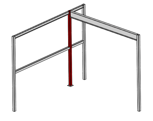
IsoView_bxop8x.png

As you can see, there is one large roof beam (initial guess is W18x60) at the top of the approximately 18' high HSS column (7" x 7" x 5/16"). Two other smaller beams (let's say a W8) also connect to the top of this HSS column. At approximately 2/3 height, girts connect into the column as well.
The client was under the impression that some simple prop shores would be able to support all of these beams during column replacement. Since the column is located on an exterior wall and that it provides a connection for girts, I don't believe the single prop shores will provide any of the necessary lateral support to resist wind loads. So my questions are as follows.
1) Would it be reasonable to design the falsework for lateral loads which are caused by a 10 year wind? The process of removing the column and replacing it with a new one should take no longer than a week or two at max. Designing temporary falsework for a 50 year wind seems like overkill.
2) I have been given no information on the reaction forces at the column connections. Designing the falsework to support 50% of the beam shear capacity (as notes state in structural drawing) seems unnecessary. I plan to use the dead loads from the beams themselves along with the dead load of the roof slab where necessary. I will also use the live load of 1.9 kPa as stated in the standard for falsework and formwork S269.1-16. Does this seem reasonable?
3) Any recommendations on how to laterally brace those girts once the column is removed?
A few more snapshots of the drawings.
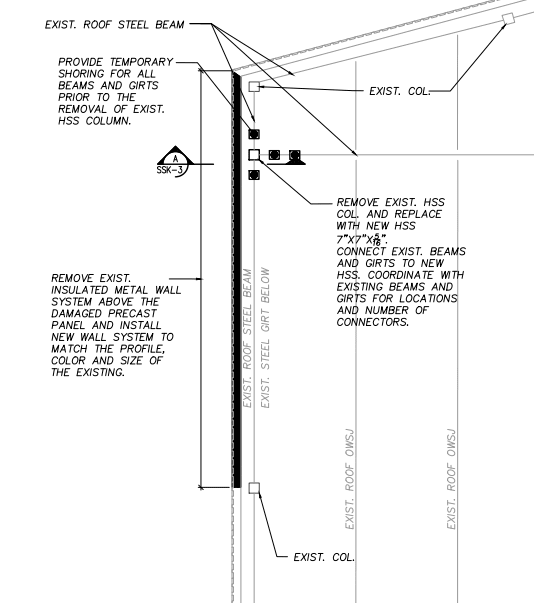
Plan_View_irtsv4.png


Section_View_v8ypsw.png


Your insightful comments are appreciated.
 
Replies continue below

Recommended for you

In terms of the wind loads considered, I would recommend reviewing ASCE 37-14 "Design Loads on Structures During Construction" - it provides guidance on how to reduce wind loads for short durations in conditions like this.

In terms of vertical loads, I would typically consider all dead loads present, and include at least a nominal live load for workers who could be in the area during the work.

In my experience, cables down to existing slab and/or concrete dead man have been used to resist lateral loads.

Hope this helps

 
Deener said:
I don't believe the single prop shores will provide any of the necessary lateral support to resist wind loads.

See if any needed lateral bracing can be provided elsewhere on the building (away from the work area). Don't want to clutter the work area any more than necessary.

Falsework is often considered part of a Contractor's means & methods. Unless your client is the Contractor (or whoever will perform the work), limit how much detail design you perform. The note "Provide temporary shoring for all beams..." shown on the drawing looks good to me. Adding a requirement that Contractor's falsework plan requires your approval may be all that is needed.

[idea]
 
You should be able to fit a commercially available shoring system under the large beam. I don’t know what the magnitude of the loads are, but I’ve dealt with shoring up bridges for a while and the XPS-60 shoring system is pretty versatile. It has a 60 kip capacity per leg. That large beam is probably carrying the most load. The exterior walls can probably be shored up with some simple timber columns.

I do a lot of construction engineering. To save time on analysis, I often just determine the capacity of the member being worked on or replaced and put something in temporary that gives the same capacity.

There are new provisions for wind loads during construction. There is a reduction coefficient and the loads should be quite a bit lower than that of a permanent design, but again, if you put up temporary members with equal or larger capacity than the permanent member then you shouldn’t have to do any wind load analysis.
 
You could put a shoring tower (scaffold) below your big beam, and then use the shoring tower to secure some lateral braces to the W8's.

Alternatively, have you considered installing a new column adjacent to the existing (below the large beam) and then bracing the damaged column with the new? This would save you the cost of shoring and a lot of demolition.
 
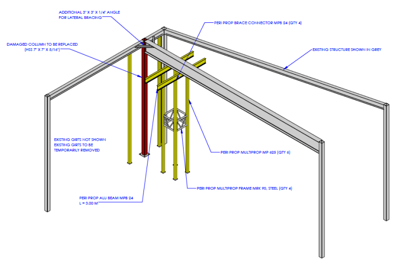
All very useful points. Thanks so much for your input. The reduction on wind loads during construction is quite useful. I've decided to brace the W8's back into the W24 beam with angle. I have also used a peri multiprop tower (as suggested) to support the W24 beam. At the request of the contractor, I have placed the tower 7ft back from the column so this portion of the W24 beam is cantilevered temporarily. Stresses in the beam itself remain incredibly low. Deflections aren't a concern either. I realize there is a moment in the W24 where it is supported by the falsework tower but I don't see that being a big issue. Can anyone think of potential issues due to this moment at the support of the falsework?
@TheRick109 - The XPS-60 shoring system sounds like it has better capacity than the peri props our contractor is using (13 kip per prop). I'll keep those in mind for next time, thanks.
@Canpro - There's lots of damage to the exterior wall so a large portion of that is being replaced anyway. I like the idea of bracing the damaged column. I think the building owner wants it replaced for aesthetics as well. Decision is out of my hands :)
Shoring_Overview_qdkxee.png
 
A few comments

a) In the past, I have often used shoring towers in this manner, though I would typically use two layers of shoring beams (Peri Prop Alum Beam in your sketch), with the top layer running perpendicular to the beam to be supported (centered on the tower), and the lower beams parallel to the beam to be supported. This ensures that the tower is evenly loaded (better for stability), and prevents the possibility of the cantilevered W24 from lifting up off of one side of the tower.
b) In terms of the analysis of the W24, I would mention that the compression flange of the beam will be on the bottom, and the unbraced length could be different, impacting bending capacity; plus, you may need to look at web crippling / web yielding at the support point.
c) Depending on the installation method used for the tower, you may want to consider the base to height ratio of the tower, in regards to the scaffolding regulations (OSHA 1926 in USA) - I believe that 4:1 is the maximum allowable.


Status
Not open for further replies.

Part and Inventory Search

Sponsor