Continue to Site

Eng-Tips is the largest engineering community on the Internet

Intelligent Work Forums for Engineering Professionals

  • Congratulations MintJulep on being selected by the Eng-Tips community for having the most helpful posts in the forums last week. Way to Go!

Fan start up resonance 1

Status
Not open for further replies.

canwesteng

Structural
May 12, 2014
1,628
This might be best suited to a mechanical forum, but I'm wondering about start up forces for a fan. The vendor has placed the fan (running around say 20Hz) on soft springs, to reduce the dynamic forces on the supporting floor. Obviously as the fan starts up, it will have to run through the natural frequency of the springs, but only for an instant. I don't want to hit the shut down vibration level (ideally not even the alarm level) when the fan runs through this frequency, but I'm wondering if it's a concern as it should pass through fairly quickly. Preference of course would be to swap the springs with fabreeka or other damper but the question still stands.
 
Replies continue below

Recommended for you

In general, a fan has good load characteristics for an electric motor. Fans require low power to start, with required power input increasing with the cube of the fan's rotational speed. Unless the resonant frequency occurs at very low RPM, the motor should quickly accelerate through that frequency.

[idea]
 
I've typically compared such scenarios to the short-term performance criteria in ACI 351.3R-04 (see Fig. 3.9). If it's something that can (say) run for 10 days without issue, I do not give it much thought. (Although I try to keep in mind how often the equipment shuts down and starts up. Basically you figure a equivalent number of cycles in the "rough" range.)

You also have to make a call as to human tolerance for this (again depending on the frequency of shut down/start up times).

If you are worried about hitting a shut down level.....that's something you just have to be sure you don't hit. (Analysis will tell you that.)

 
Analysis could tell me that, if I knew how many cycles it would run at resonance. If start up is quick enough that there isn't even a full cycle at resonance it's clearly no concern, but a couple 100 might be.
 
Analysis could tell me that, if I knew how many cycles it would run at resonance. If start up is quick enough that there isn't even a full cycle at resonance it's clearly no concern, but a couple 100 might be.

Why not look at the time-history plot from your output? If it passes through resonance....you should see the spike in displacement early on.
 
The time history plot is going to be at resonance, or at only one frequency. I only have STAAD or SAP2000, not sure what software you are using, but I can either see a time history plot at one frequency, or steady state response at all frequencies (which makes sense when starting up a centrifuge for example, because if it's full it's starting up slowly).
 
The time history plot is going to be at resonance, or at only one frequency. I only have STAAD or SAP2000, not sure what software you are using, but I can either see a time history plot at one frequency, or steady state response at all frequencies (which makes sense when starting up a centrifuge for example, because if it's full it's starting up slowly).

I'm not sure I follow your statement. The displacement plot will/should reflect the fact you have passed through resonance and are running at the operating frequency. It should be apparent from the plot how long you are in this danger zone.

If you are not seeing a transient phase of motion.....either your assumption is incorrect about the fact you are going through resonance.....or there is a issue with your input function (possibly with the number of cycles you are running or perhaps your Δt).

 
At operating frequency we're nowhere near resonance, otherwise the isolators wouldn't even be installed. The fan is shut off, at 0Hz, turned on, and runs through every frequency up to 20 Hz until it holds there, and everything reaches steady state vibration. The isolators will have some natural frequency that is perhaps 1/3 of that of the fan, so the transient response is important here, but the question is how many cycles does the fan operate near the natural frequency of the isolators and is this a concern.
 
The isolators will have some natural frequency that is perhaps 1/3 of that of the fan, so the transient response is important here, but the question is how many cycles does the fan operate near the natural frequency of the isolators and is this a concern.

I guess I don't see the mystery (unless the isolators are proving to be difficult to model). I use STAAD Pro myself for this all the time. And one axis of the time-history plot is always time (in seconds). If it's spiking over X amount of seconds.....and the equipment is running Y amount of Hertz (which is cycles per second).....I would think that would be pretty straight forward (i.e. to get the number of cycles in this zone).

 
Nothing is hard to model (although I'd just check the isolators by hand). STAAD is only checking a single frequency, usually your operating frequency. I know vibrations at the operating frequency are fine, and I know steady state vibrations at the natural frequency of the isolators are likely not. When the equipment passes through the natural frequency of the isolators on start-up, I need to know if I hit the shut down level of the fan. That means I need to know how many cycles the fan operates near enough to that frequency to find out where I am on the transient response.
 
There are a number of different analyses you could do:

1) Run the steady state analysis at the natural frequency of the support springs. That will give you a worst case scenario.
2) You should be able to manually create a time history input that varies the frequency of the input as the fan ramps ups its speed. When I was working on the RISA implementation of time history analysis, I did this. Hopefully, I still have the spreadsheet that I used to do this.... If so, then if you give me some basic data then I can generate this for you in excel and give it to you. I would need:
a) Ramp time: Meaning the time between when you start the fan and when it achieves it operating RPM.
b) It's operating RPM (about 20 Hz, right)
c) Whether the frequency increases linearly or quadratically during the ramp up.

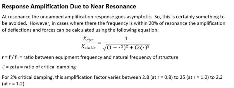
3) Based on the assumed damping, you could create a dynamic amplification factor by hand just to see what order of magnitude we're talking about.
image_ienfrx.png
 
Would you be able to share the excel file? I'm not going to fire something up without checking it, and I'm not asking anyone on the forum to do any real work for me for free.
 
When the equipment passes through the natural frequency of the isolators on start-up, I need to know if I hit the shut down level of the fan. That means I need to know how many cycles the fan operates near enough to that frequency to find out where I am on the transient response.

Seems to me like you could figure that out based on the time-history plot and what I told you. But then again I'm not sure what role the number of cycles will play in this (as far as shut off goes). Granted there are probably a million gizmos out there at this point.....but most alarm/shut off switches I am familiar with kick in once the level of vibration exceeds a certain amount. I.e. it will shut off/alarm regardless of the number of cycles.

But as I said.....a lot of widgets out there.
 
I see two questions here.

1. How many start up/shutdown cycles can the vibration isolation system take? This is best determined through testing. The supplier of the vibration isolation system may be able to help quantify this.

2. Sensitivity of the structural support system to vibration? From the sound it the OP has determined that support system's natural frequency is outside of the equipments operating frequency. Now he wants to know if the likelyhood of damage to the support system causes by start up/shutdown. Josh and War had good answers to approach this analysis.
 
Neither of those are my question... SRE and Joshplum hit the nail on the head.
 
Canwesteng -

Well, I couldn't locate my original Excel file. So, I tried to recreate it. I'm remembering how tricky it was to get right. It is attached.... Though this only works for the linear frequency increase. I am pretty sure the linear one is correct as I have tested it out a good bit on the plots page to make sure everything looked right.
 
Also, one thing I remember now after re-creating that Excel file.... This is known as a "chirp function". So, if you google it, there are places (wikipedia?) that have the functions listed. Obviously, you have to test them out because they aren't always 100% correct. Which is why I created the plots for the Excel spreadsheet.
 
A fan is such an "easy" load for an electric motor that Josh's equations should be a reasonable approximation of system transient performance. That would not necessary be the case for loads where a motor's real electrical/mechanical capabilities are a factor and slow down ramp-up time.

canwesteng said:
The isolators will have some natural frequency that is perhaps 1/3 of that of the fan, so the transient response is important here...

At that rotational speed (6.7 Hz +) the fan / motor should be accelerating like crazy... doubt there will be any problem passing though resonance frequency.

[idea]
 
I'm of the same opinion, would like to just back of the napkin calc this and say ok, rough estimate says peak amplitude is an order of magnitude away from shutdown level, and away we go.
 
Status
Not open for further replies.

Part and Inventory Search

Sponsor