Eng-Tips is the largest engineering community on the Internet

Intelligent Work Forums for Engineering Professionals

Fanuc Wear Compensation in NX CAM?

Status
Not open for further replies.

TheeCircle

Civil/Environmental
Sep 5, 2013
149
0
0
CA
Hi,

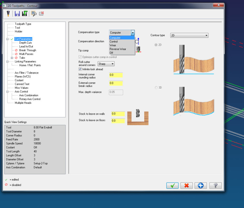
I would like to have the option for wear compensation for our Fanuc 3 Axis VMC.

I have my post almost finished but I can not figure this one out.

Any ideas?

Thank you

John
 
Replies continue below

Recommended for you

Regular cutcom (G40/41/42) should be there out of the box.
Be sure you turn it on in Non Cutting Moves, More, Cutter Compensation.

Mark Rief
NX CAM Customer Success
Siemens PLM Software
 
Hi Mark,

That gives me the following options:

None
Final Finish Pass
All Finish Pass

I don't see "wear"?

Sorry for not being more up to speed!

Thank you for any help you can offer!

John


What do you expect to see as output from the post?

Typically G41/G42 with a D word are used for Wear compensation.

John Joyce
N.C. Programming Supervisor
Barnes Aerospace, Windsor CT
NX7.5, NX9.0, NX10.0(Testing)
Vericut7.3.3
 
Hi John,

I am in the process of changing software so the learning curve is steep!

I want to know what to select within the tool path/ operation to have the wear option. Within my old software I had the compensation option of either:

Computer
Wear
Reverse Wear
Off

Any help is greatly appreciated!

Thank you

John


I don't understand what "wear" function you are asking about.
Repeating John's question - what output are you expecting in the G code?

Mark Rief
NX CAM Customer Success
Siemens PLM Software
 
Hi Mark,

With my my old software I had the option of selecting the options listed in my last post, that in turn would dictate the compensation. So for "computer comp" it would offset the tool within the CAM file and post the code without a G41/G42. If I wanted to engrave a stick font I would post with "off comp" and it would follow the tip of the tool without any offsets within the CAM program or on the control of the machine tool. If I selected "wear comp" it would post the G41/G42 and the offsets would then be finalized on the machine control. Hopefully I am explaining this correctly.

Not sure if I am over thinking this or not.

Here is some code:

This is "Computer Comp":


N100 G100
N110 T9
N120 M06
N130 G100
N140 (MAX - Z2.)
N150 (MIN - Z0.)
N160 G00 G90 G54 X-1.4549 Y1.7889 S5000 M03
N170 G43 H9 Z2. M08
N180 Z.325
N190 G01 Z0. F7.
N200 Y1.6764 F15.
N210 G03 X-1.3987 Y1.6201 I.0562 J0.
N220 G01 X2.0185
N230 G02 X2.1123 Y1.5264 I0. J-.0937
N240 G01 Y-1.5264
N250 G02 X2.0185 Y-1.6201 I-.0938 J0.

This is "Wear Comp":

N100 G100
N110 T9
N120 M06
N130 G100
N140 (MAX - Z2.)
N150 (MIN - Z0.)
N160 G00 G90 G54 X-1.4549 Y1.7889 S5000 M03
N170 G43 H9 Z2. M08
N180 Z.325
N190 G01 Z0. F7.
N200 G41 D9 Y1.6764 F15.
N210 G03 X-1.3987 Y1.6201 I.0562 J0.
N220 G01 X2.0185
N230 G02 X2.1123 Y1.5264 I0. J-.0937
N240 G01 Y-1.5264
N250 G02 X2.0185 Y-1.6201 I-.0938 J0.
N260 G01 X-2.0185
N270 G02 X-2.1123 Y-1.5264 I0. J.0937

This is "Comp Off":


N100 G100
N110 T9
N120 M06
N130 G100
N140 (MAX - Z2.)
N150 (MIN - Z0.)
N160 G00 G90 G54 X-1.4549 Y1.6951 S5000 M03
N170 G43 H9 Z2. M08
N180 Z.325
N190 G01 Z0. F7.
N200 Y1.5826 F15.
N210 G03 X-1.3987 Y1.5264 I.0562 J0.
N220 G01 X2.0185
N230 Y-1.5264
N240 X-2.0185
N250 Y.9065
N260 X-1.3987 Y1.5264

Thank you for all of you help!

John


Sounds like you were a mastercam user, are you expecting something like this?

wear_ddzdmv.jpg


Wear in NX is tool tangent, with cutter comp. You can choose left or right for wear or reverse wear


Regards
Greg
 
I think what you want in NX is to output the contact point of the tool rather than the centerline.
On the tool dialog you can set the Tracking Point to the tool diameter and tip. Then on the non-cutting moves you can choose to output the Contact/tracking point data.

I think this is what your looking for.


John Joyce
N.C. Programming Supervisor
Barnes Aerospace, Windsor CT
NX7.5, NX9.0, NX10.0(Testing)
Vericut7.3.3
 
I'll take some more guesses at translating...

What you call "computer" is the norm in NX. The tool CL is programmed the tool radius away from the part.

What you call "wear" is Cutcom (Cutter Compensation) in NX. The operator can adjust the path left or right of the programmed path.

What you call "contol" is Cutcom with contact/tracking output in NX. The tool contact point (part edge) is output instead of the CL. The operator enters the full radius of the tool to adjust the path away from the part.

If this is right, now you know what to search for in the help :*)


Mark Rief
NX CAM Customer Success
Siemens PLM Software
 
Status
Not open for further replies.
Back
Top